
Data Sheet

Page 58
nRF51822 Product Specification v3.1
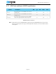
8.10 I2C compatible Two Wire Interface (TWI) specifications
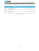
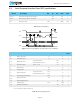
Table 48 TWI specifications
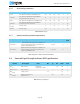
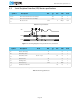
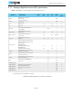
Figure 14 SCL/SDA timing
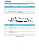
Table 49 TWI timing parameters
Symbol Description Note Min. Typ. Max. Units
Test
level
I
2W100K
Run current for TWI at 100 kbps. 380 µA 1
I
2W400K
Run current for TWI at 400 kbps. 400 µA 1
f
2W
Bit rates for TWI. 100 400 kbps N/A
t
TWI,START
Time from STARTRX/STARTTX task is
given until start condition.
Low power mode.
1
Constant latency mode.
1
1. For more information on how to control the sub power modes, see the nRF51 Series Reference Manual.
3
1
4.4
µs 1
Symbol Description
Standard
Min. Max.
Fast
Min. Max.
Units
Test
level
f
SCL
SCL clock frequency. 100 400 kHz 1
t
HD_STA
Hold time for START and repeated
START condition.
5200 1300 ns 1
t
SU_DAT
Data setup time before positive
edge on SCL.
300 300 ns 1
t
HD_DAT
Data hold time after negative
edge on SCL.
300 300 ns 1
t
SU_STO
Setup time from SCL goes high
to STOP condition.
5200 1300 ns 1
t
BUF
Bus free time between STOP and
START conditions.
4700 1300 ns 1
1/f
SCL
SCL
SDA
t
HD_SDA
t
SU_DAT
t
HD_DAT
t
BUF
t
SU_STO