
Data Sheet

Page 54
nRF51822 Product Specification v3.1
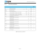
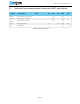
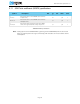
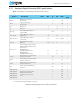
8.5.6 Radio timing parameters
Table 40 Radio timing
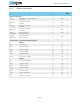
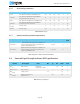
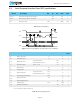
8.5.7 Antenna matching network requirements
Table 41 Optimum differential load impedance
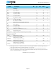
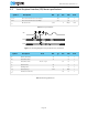
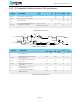
8.6 Received Signal Strength Indicator (RSSI) specifications
Table 42 RSSI specifications
Symbol Description 250 k 1 M 2 M BLE Jitter Units
t
TXEN
Time between TXEN task and READY event. 132 132 132 140 0 µs
t
TXDISABLE
Time between DISABLE task and DISABLED
event when the radio was in TX.
10 4 3 4 1 µs
t
RXEN
Time between the RXEN task and READY event. 130 130 130 138 0 µs
t
RXDISABLE
Time between DISABLE task and DISABLED
event when the radio was in RX.
0 0 0 0 1 µs
t
TXCHAIN
TX chain delay. 5 1 0.5 1 0 µs
t
RXCHAIN
RX chain delay. 12.5 3 2 3 0 µs
Symbol Description Min. Typ. Max. Units
Test
level
Z
QFN48,ANT1,2
Optimum differential impedance at 2.4 GHz seen
into the matching network from pin ANT1 and
ANT2 on the QFN48 packet.
15 + j85 1
Z
WLCSP,ANT1,2
Optimum differential impedance at 2.4 GHz seen
into the matching network from pin ANT1 and
ANT2 on the WLCSP packet.
12.6 + j106 1
Symbol Description Note Min. Typ. Max. Units
Test
level
RSSI
ACC
RSSI accuracy.
Valid range
-50 dBm to -80 dBm.
±6 dB 2
RSSI
RESOLUTION
RSSI resolution. 1 dB 1
RSSI
PERIOD
Sample period. 8.8 µs 1
RSSI
CURRENT
Current consumption in
addition to I
RX
.
250 µA 1