
Data Sheet

Page 47
nRF51822 Product Specification v3.1
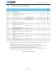
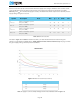
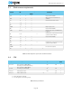
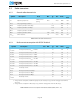
Table 32 Power management
t
1V7
Startup time for 1V7 regulator 2 3.6 µs 1
I
1V7
Current drawn by 1V7 regulator 105 µA 2
F
DCDC
DC/DC converter current
conversion factor.
0.65
4
1.2
4
1
1. Add 1 μA to the current value if the device is used in Low voltage mode.
2. This number includes the current used by the automated power and clock management system.
3. For details on 1 MHz mode, see Section 4.2 “Timer/counters (TIMER)” on page 32.
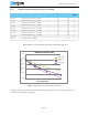
4. F
DCDC
will vary depending on VDD and internal radio current consumption (I
DD
). Please refer to the nRF51 Series Refer-
ence Manual, v3.0 or later, for a method to calculate I
DD,DCDC
. See Figure 11 on page 50 for a DC/DC conversion factor
chart.
Symbol Description Note Min. Typ. Max. Units
Test
level