
Data Sheet

Page 44
nRF51822 Product Specification v3.1
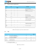
8.2 Power management
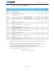
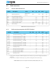
Table 28 Power Fail Comparator
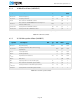
Table 29 Pin Reset
Symbol Description Note Min. Typ. Max. Units
Tes t
level
V
POF
Nominal power level warning
thresholds (falling supply voltage).
Accuracy as defined by V
TOL
2.1
2.3
2.5
2.7
V2
V
TOL
Threshold voltage tolerance. ±5 % 3
V
HYST
Threshold voltage hysteresis.
V
POF
= 2.1 V
V
POF
= 2.3 V
V
POF
= 2.5 V
V
POF
= 2.7 V
46
62
79
100
mV 3
Symbol Description Min. Typ. Max. Units
Tes t
level
t
HOLDRESETNORMAL
Hold time for reset pin when doing a pin reset.
1
1. SWDCLK pin must be kept low during reset.
0.2 µs 1
t
HOLDRESETDEBUG
Hold time for reset pin when doing a pin reset
during debug.
1,2
2. Bit 0 in the RESET register in the power management module must be set to 1 to enable reset during debug.
100 µs 1