
Data Sheet

Page 41
nRF51822 Product Specification v3.1
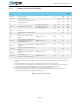
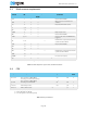
8.1.3 32 MHz crystal oscillator (32M XOSC)
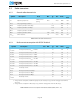
Table 23 32 MHz crystal oscillator
Symbol Description Note Min. Typ. Max. Units
Test
level
f
NOM,X32M
Crystal frequency. 32 MHz N/A
f
TOL,X32M
Frequency tolerance.
1
1. The Frequency tolerance relates to the amount of time the radio can be in transmit mode. See Table 38 on page 51.
±50
2
2. Includes initial tolerance of the crystal, drift over temperature, aging and frequency pulling due to incorrect load capac-
itance.
ppm N/A
f
TOL,X32M,BLE
Frequency tolerance, Bluetooth low
energy applications.
1
±40
2
ppm N/A
R
S,X32M
Equivalent series resistance.
C0 ≤ 7 pF, C
L,MAX
≤ 12 pF
C0 ≤ 5 pF, C
L,MAX
≤ 12 pF
C0 ≤ 3 pF, C
L,MAX
≤ 9 pF
30
40
50
60
80
100
N/A
N/A
N/A
P
D,X32M
Drive level. 100 µW N/A
C
pin
Input capacitance on XC1 and XC2
pads.
4 pF 1
I
X32M
Run current for 32 MHz crystal
oscillator.
SMD 2520 CL = 8 pF
500
3
3. This number includes the current used by the automated power and clock management system.
µA 1
I
X32M,1M
Run current for the 32 MHz crystal
oscillator when used only for a
Timer at 1 MHz or less.
SMD 2520 CL = 8 pF
300
3
µA 1
I
STBY,X32M
Standby current for 32 MHz crystal
oscillator.
4
4. Standby current is the current drawn by the oscillator when there are no resources requesting the 32M, meaning there
is no clock management active (see Table 33 on page 48). This value will depend on type of crystal.
SMD 2520 CL = 8 pF 30 µA 1
I
START,XOSC
Startup current for 32 MHz crystal
oscillator.
1.1 mA 3
t
START,XOSC
Startup time for 32 MHz crystal
oscillator.
SMD 2520 CL = 8 pF 300
400
5
5. Crystals with other specification than SMD 2520 may have much longer startup times.
µs 1
t
START,X32M
Total startup time
(t
START,XOSC
+
debounce period).
6
6. This is the time from when the crystal oscillator is powered up until its output becomes available to the system. It
includes both the crystal startup time and the debounce period.
SMD 2520 CL = 8 pF 750 µs 1