
Data Sheet

Page 39
nRF51822 Product Specification v3.1
8 Electrical specifications
This chapter contains electrical specifications for device interfaces and peripherals including radio
parameters and current consumption.
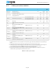
The test levels referenced are defined in Table 21 .
Table 21 Test level definitions
8.1 Clock sources
8.1.1 16/32 MHz crystal startup
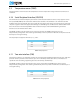
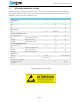
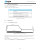
Figure 9 Current drawn at oscillator startup
Figure 9 shows the current drawn by the crystal oscillator (XOSC) at startup. The t
START,XOSC
period is the
time needed for the oscillator to start clocking. The length of t
START,XOSC
is dependent on the crystal
specifications.
The period following t
START,XOSC
to the end of t
START,X16M
/t
START,X32M
is fixed. This is the debounce period
where the clock stabilizes before it is made available to rest of the system.
Test level Description
1
Simulated, calculated, by design (specification limit) or prototype samples
tested at NOC.
2
Parameters have been verified at Test level 1 and in addition:
Prototype samples tested at EOC.
3
Parameters have been verified at Test level 2 and in addition:
Production samples tested at EOC in accordance with JEDEC47.
4
Parameters have been verified at Test level 3 and in addition:
Production devices are limit tested at NOC.
t
START ,XOSC
t
START,X16M
/t
START,X32 M
I
START,XOSC
Enable XOSC
XOSC Ready