
Data Sheet

Page 35
nRF51822 Product Specification v3.1
4.12 Universal Asynchronous Receiver/Transmitter (UART)
The Universal Asynchronous Receiver/Transmitter offers fast, full-duplex, asynchronous serial
communication with built-in flow control (CTS, RTS) support in hardware up to 1 Mbps baud. Parity
checking is supported.
The GPIOs used for each UART interface line can be chosen from any GPIO on the device and are
independently configurable. This enables great flexibility in device pinout and efficient use of board space
and signal routing.
4.13 Quadrature Decoder (QDEC)
The quadrature decoder provides buffered decoding of quadrature-encoded sensor signals. It is suitable for
mechanical and optical sensors with an optional LED output signal and input debounce filters. The sample
period and accumulation are configurable to match application requirements.
4.14 Analog to Digital Converter (ADC)
The 10 bit incremental Analog to Digital Converter (ADC) enables sampling of up to 8 external signals
through a front-end multiplexer. The ADC has configurable input and reference prescaling, and sample
resolution (8, 9, and 10 bit).
Note: The ADC module uses the same analog inputs as the LPCOMP module (AIN0 - AIN7 and
AREF0 - AREF1). Only one of the modules can be enabled at the same time.
4.15 GPIO Task Event blocks (GPIOTE)
A GPIOTE block enables GPIOs on Port 0 to generate events on pin state change which can be used to carry
out tasks through the PPI system. A GPIO can also be driven to change state on system events using the PPI
system. Low power detection of pin state changes on Port 0 is possible when in System ON or System OFF.
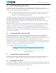
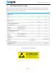
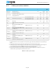
Table 17 GPIOTE properties
4.16 Low Power Comparator (LPCOMP)
In System ON, the block can generate separate events on rising and falling edges of a signal, or sample the
current state of the pin as being above or below the threshold. The block can be configured to use any of the
analog inputs on the device. Additionally, the low power comparator can be used as an analog wakeup
source from System OFF or System ON. The comparator threshold can be programmed to a range of
fractions of the supply voltage.
Note: The LPCOMP module uses the same analog inputs as the ADC module (AIN0 - AIN7 and
AREF0 - AREF1). Only one of the modules can be enabled at the same time.
Instance Number of GPIOTE channels
GPIOTE 4