
Data Sheet

Page 29
nRF51822 Product Specification v3.1
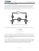
3.6.2 32.768 kHz crystal oscillator
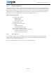
The 32.768 kHz crystal oscillator is designed for use with a quartz crystal in parallel resonant mode. To
achieve correct oscillation frequency, the load capacitance must match the specification in the crystal data
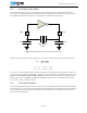
sheet. Figure 8 shows how the crystal is connected to the 32.768 kHz crystal oscillator.
Figure 8 Circuit diagram of the 32.768 kHz crystal oscillator
The load capacitance (CL) is the total capacitance seen by the crystal across its terminals and is given by:
C1’ = C1 + C_pcb1 + C_pin
C2’ = C2 + C_pcb2 + C_pin
C1 and C2 are ceramic SMD capacitors connected between each crystal terminal and ground. C_pcb1 and
C_pcb2 are stray capacitances on the PCB. C_pin is the pin input capacitance on the XC1 and XC2 pins, see
Section 8.1.5 “32.768 kHz crystal oscillator (32k XOSC)” on page 42. The load capacitors C1 and C2 should
have the same value. See Chapter 11 “Reference circuitry” on page 76 for the capacitance value used for
C_pcb1 and C_pcb2 in reference circuitry.
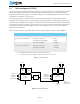
3.6.3 32.768 kHz RC oscillator
The 32.768 kHz RC low frequency oscillator may be used as an alternative to the 32.768 kHz crystal oscillator.
It has a frequency accuracy of less than ± 250 ppm in a stable temperature environment or when calibration
is periodically performed in changing temperature environments. The 32.768 kHz RC oscillator does not
require external components.
C1 C2
32.768 kHz
crystal
XL1 XL2
CL
C1' C2'
C1' C2'+
----------------------------
=