
Data Sheet

Page 23
nRF51822 Product Specification v3.1
3.4 Power management (POWER)
3.4.1 Power supply
nRF51 supports three different power supply alternatives:
• Internal LDO setup
•DC/DC converter setup
• Low voltage mode setup
See Table 20 on page 38 for the voltage range on the different alternatives. See Chapter 11 “Reference
circuitry” on page 76 for details on the schematic used for the different power supply alternatives.
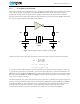
3.4.1.1 Internal LDO setup
In internal LDO mode the DC/DC converter is bypassed (disabled) and the system power is generated
directly from the supply voltage VDD. This mode could be used as the only option or in combination with
the DC/DC converter setup. See DC/DC converter section for more details.
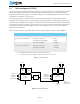
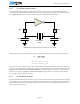
3.4.1.2 DC/DC converter setup
The nRF51 DC/DC buck converter transforms battery voltage to lower internal voltage with minimal power
loss. The converted voltage is then available for the linear regulator input. The DC/DC converter can be
disabled when the supply voltage drops to the lower limit of the voltage range so the LDO can be used for
low supply voltages. When enabled, the DC/DC converter operation is automatically suspended between
radio events when only the low current regulator is needed internally.
This feature is particularly useful for applications using battery technologies with nominal cell voltages
higher than the minimum supply voltage with DC/DC enabled. The reduction in supply voltage level from a
high voltage to a low voltage reduces the peak power drain from the battery. Used with a 3 V coin-cell
battery, the peak current drawn from the battery is reduced by approximately 25%.
3.4.1.3 Low voltage mode setup
Devices can be used in low voltage mode where a steady 1.8 V supply is available externally.