
Data Sheet

Page 19
nRF51822 Product Specification v3.1
3 System blocks
The chip contains system-level features common to all nRF51 series devices including clock control, power
and reset, interrupt system, Programmable Peripheral Interconnect (PPI), watchdog, and GPIO.
System blocks which have a register interface and/or interrupt vector assigned are instantiated in the device
address space. The instances of system blocks, their associated ID (for those with interrupt vectors), and base
addresses are found in Table 18 on page 36. Detailed functional descriptions, configuration options, and
register interfaces can be found in the nRF51 Series Reference Manual.
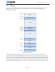
3.1 CPU
The ARM® Cortex™-M0 CPU has a 16 bit instruction set with 32 bit extensions (Thumb-2® technology) that
delivers high-density code with a small-memory-footprint. By using a single-cycle 32 bit multiplier, a 3-stage
pipeline, and a Nested Vector Interrupt Controller (NVIC), the ARM Cortex-M0 CPU makes program
execution simple and highly efficient.
The ARM Cortex Microcontroller Software Interface Standard (CMSIS) hardware abstraction layer for the
ARM Cortex-M processor series is implemented and available for M0 CPU. Code is forward compatible with
ARM Cortex M3 based devices.