Operator’s Manual English TABLE OF CONTENTS INTENDED USE.............................................................. 2 SUMMARY AND EXPLANATION.................................... 2 PRINCIPLES OF OPERATION ....................................... 2 ATTENTION LABEL ........................................................ 4 SPECIFICATIONS........................................................... 5 GETTING STARTED....................................................... 5 SETTING SUPERVISOR OPTIONS ............
INTENDED USE The HEMOCHRON® Response Whole Blood Coagulation System is a dual-well microprocessor-controlled coagulation testing instrument with an integral test type barcode reader, RS232 communication interface capability, and a printer. The system runs coagulation tests such as Activated Clotting Time (ACT), Activated Partial Thromboplastin Time (APTT), Prothrombin Time (PT) and other specialty tests that are currently available from ITC.
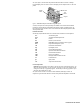
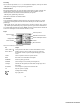
The system (Figure 1) contains a dual-well patented clot detection module. User interface is through a keypad and display panel. Test results are shown on the display panel on completion of the test, and can be printed. Display Panel Printer Test Wells Keypad Figure 1.
After a clot forms, the instrument beeps and the clotting time is displayed on the display panel. The result is also stored in the system database with the date and time the test was performed, and the assay type. If entered, the PID and OID are stored with the test result.
SPECIFICATIONS Specifications for the HEMOCHRON Response Whole Blood Coagulation System are listed below. Dimensions and Weight Depth Width Height Weight 19 cm (7.5 in) 27 cm (10.5 in) 22 cm (8.7 in) 2.90 kg (6.4 lbs) Operation Test Wells Timing Range Incubation Temperature Incubation Warm-Up Time Full-Charge Operating Time Battery Life Throughput (Full Charge) AC/DC Power Module Input Power Output Power Environmental Ambient Temperature 2 22 seconds to 1500 seconds 37 °C ±1.
Materials Provided Article HEMOCHRON Response Whole Blood Coagulation Instrument AC/DC Power Module ITC Part Number HR1283 Power cord (see note below) Seiko Thermal Paper Operator’s Manual HRDM V3.0 software program RS232 Computer Interface Cable Quantity 1 1 1 1 roll 1 1 1 Materials Required But Not Provided Article Quantity Electronic System Verification Tube 1 HEMOCHRON Test Tube Assays As Needed HEMOCHRON Liquid Quality Control As Needed Temperature Verification Tube As Needed idms v7.
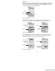
Connecting a Personal Computer The system can be connected to a personal computer using a standard NULL modem cable. 1. Obtain an RS232 cable (provided). Refer to page 39 for cable information. 2. Connect one end of the cable to the port marked COM 1 or COM 2 (Figure 2). 3. Connect the other end of the cable to an unused serial communication port on the computer. Note the location (COM 1 or COM 2) of the port. 4. Set the COM port location as described on page 19.
Prewarming The test wells can be prewarmed to 37 °C ±1.0 °C on command. On completion, 3 short beeps are emitted. Note: Refer to assay package inserts for prewarming requirements. Automatic Shutdown When operating from the battery, the system shuts down automatically after 15 minutes of inactivity. This 15-minute interval cannot be changed. When operating from the AC/DC Power Module, the system automatically shuts down after an interval of inactivity defined by the supervisor.
Display Panel Operations such as running a test and prewarming a well can be carried out simultaneously on both wells. However, commands, prompts, and test results that appear on the display panel apply to a single well. The well for which commands are displayed is designated by the position of the divider bar (the bar in which the time and remaining battery power are displayed) (Figure 3). Arrows Divider Bar Figure 3.
The arrows designate the operation that will be halted if the CANCEL key is pressed. If an operation is canceled, the arrows will point to the next operation that can be canceled. If an operation cannot be canceled, arrows are not displayed. Note: Pressing CANCEL shuts down a test, removes any related menus, sets the assay to the default assay, sets the record type to Patient, resets the OID or PIN and resets all lockouts.
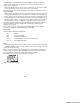
Select a command by pressing the corresponding numeral key while the command is displayed. For example, if a PID or OID/PIN is to be entered using the ID Selects command, press 1. Press a MENU key twice to display the second page of the main menu (Figure 7): Figure 7. Second Page of the Main Menu Tests The test menu is contained on four pages, accessed by selecting the ID Selects command from the first page of the main menu and then selecting 3 to display the first Test ID page (Figure 8).
To Display the Supervisor Menu: Display the second page of the main menu. 2. Press 4 to display the Enter Passcode prompt. Enter the passcode. 3. Press YES to accept. The first page of the Supervisor menu is displayed. 4. Press MENU once or twice to display the second or third page of the Supervisor menu. Note: The next or previous pages can also be displayed by pressing 0 or 9. 1. Setting the Time The time that a test is performed is automatically recorded with the test result.
Displaying the Clock The time can be displayed on the separator bar of the display panel. 1. Display the first page of the Supervisor menu. 2. Press 5 to display the Clock line. ON will be displayed after the Clock line. Note: Displaying the clock operates as a toggle. If clock is already specified (displayed as ON), it can be canceled by pressing 5 again to display OFF.
Specifying the Length of Time a PID will be Reused After a PID is entered, it can be displayed as a default entry for a specified number of hours. 1. Display the first page of the Supervisor menu. 2. Press 2 to display the PID Setup menu. 3. Press 3 to display the Enter Reuse Hrs prompt. Enter the number of hours. Note: 0 to 240 can be entered. If 0 is entered, the entered PID will not be reused. Requiring Entry of an OID or PIN 1. Display the first page of the Supervisor menu. 2.
Specifying OID, PIN, and Test Permissions for an Operator Note: HRDM V. 3.0 or higher software can be used to manage operator tables. 1. Display the first page of the Supervisor menu. 2. Press 3 to display the OID Setup menu. 3. Press 2. The Edit User Codes list is displayed: 4. 5. 6. 7. 8. Note: Up to 504 users can be specified. Locate the user record. If needed, press 0 or 9 to display the next or preceding page. Press the numeral key corresponding to the user.
Specifying QC Lockouts 1. Display the second page of the Supervisor menu. 2. Press 6 to display the first page of the QC Lockout menu: To specify whether LQC must be run at specified intervals, press 1 until the desired selection is displayed: • - designates that LQC testing will not be monitored by the instrument. • 1 designates that a single level of LQC per well must be tested at specified intervals. • 2 designates that two levels of LQC per well must be tested at specified intervals. 4.
Suppressing Results Display During a QC Test Display of the clotting time during a QC test (on the screen, printed result, and in the database) can be suppressed. 1. Display the second page of the Supervisor menu. 2. Press 6 to display the QC Lockout menu. Press MENU or 0 to display the second page. 3. Press 1 to hide the results. Y is displayed. Note: Press the numeral key again to select the alternate choice.
Downloading Records Patient and QC records can be downloaded to a personal computer from the system. ITC data management software programs can be installed on the personal computer to which the records are being downloaded to provide the reporting functions. 1. Connect the COM 1 or the COM 2 port of the HEMOCHRON Response to the personal computer. 2. Using the corresponding MENU key (MENU 1 for the COM 1 port, MENU 2 for the COM 2 port) display the second page of the Supervisor menu. 3. Press 4.
Enabling Display of Remaining Battery Power The amount of power remaining in the battery can be displayed either as a numerical percentage or as a bar indicator. 1. Press 1 in Set Outputs. YES is displayed after the Battery % line: 1 – Battery % - YES 2. Press 1 again to display a graph of remaining battery power. NO is displayed. Note: The battery power display disappears when the instrument is connected to an electrical outlet using the AC/DC Power Module.
Enabling Logging of Data The data-logging feature is used to send raw data, obtained during an assay, to an external computer or printer. This feature is most useful for troubleshooting. Note: An external printer or computer must be connected and enabled before the data-logging feature can be operated. Well 1 data are sent to COM 1 and Well 2 data are sent to COM 2. 1. Press 7 in Set Outputs to enable data logging.
CUSTOMIZING THE PRINTED HEADING The heading at the top of each printout can be customized. 1. Press MENU twice and press 3 to display the Print Heading screen. The cursor is positioned on the first character of the heading and the selection block is positioned at the space: Cursor Selection Block 2. 3. 4. 5.
Prewarming a Well Certain tests require prewarming prior to blood sample introduction. Note: Consult individual test package inserts for the required prewarming time. 1. Press MENU to display the first page of the main menu. 2. Press 3 to display the Prewarm Well menu. 3. Press the numeral key corresponding to the length of prewarming time. 4. Insert the tube to be prewarmed into the well. The time remaining (in seconds) until prewarming is complete is displayed. 5.
To Specify the Test: Display the ID Selections menu. Press 3 to display the first page of tests. 2. If the test is on the first list, select the test by pressing the corresponding numeral key. An arrow will be displayed after the number of the selected test. 3. If the test is not displayed on the first page, display subsequent lists by pressing the MENU key until the test is displayed. Then select the test by pressing the corresponding numeral key. 4. Press YES to save the test.
Starting the Test Consult the individual test package insert to determine the volume of sample and appropriate test procedure to use. 1. Dispense the sample into the test tube and simultaneously press the START key. A beep will signal the start of the test and timing of the test begins. 2. Mix the contents of the test tube. Note: A test is automatically terminated if a tube is not detected within 60 seconds after pressing START. 3. Insert the test tube in the well (Figure 9 below).
Aborting a Test A test can be aborted once the timing has begun. 1. Press CANCEL. The instrument will display Hit YES to Abort. 2. Press YES to stop the test. Note: The test can also be aborted by removing the tube after the test has been running for 15 seconds. Results Display While a test is running, the test name, temperature, PID (if entered), and the elapsed time after starting the test are displayed.
Storage of Results Patient and quality control test results are automatically stored when the test is completed. The OID, PID or QC tag, and date and time each test was run are stored with the results for each test. Instrument Shutdown To shut down the system, press either START key and hold it down. Or, select 7 - System Off from the first page of the main menu.
QUALITY CONTROL (QC) The Joint Commission on Accreditation of Healthcare Organizations (JCAHO) recommends that medical and laboratory instrumentation be enrolled in a quality assurance program adequate in maintaining accurate and reliable performance of the equipment. Complete records of such quality control must be kept. Routine quality control testing should be part of a comprehensive quality assurance program.
When the correct ESV serial number is displayed, press YES. Upon completion of the test and removal of the ESV tube from the well, the result is stored in the database. Compare the result with the number of seconds selected in the first step. 7. Repeat, using the 300 second or 500 second button for the first well. Then, repeat the entire test on the second well. Results are acceptable if within 10 seconds of the selected times. Note: Contact ITC if the results are not within range.
911 Attempts The instrument can be unlocked by an authorized operator for a specified number of additional patient tests after the maximum time between controls has been exceeded. This option is available if the 911 Attempts option is enabled (page 16). Note: The number of 911 Attempts that can be used to override mandatory QC is specified during setting of Supervisory Options. A dollar sign ($) will be included on the result printout of any test run using the 911 Attempts option.
RESULTS MANAGEMENT Overview Up to 600 patient test results and 300 quality control test results per test well are stored in the instrument database. In addition to test results, the date and time of each test, PID (if entered) or QC tag, and OID (if specified) are also stored. The stored results can be grouped by type of result (patient or QC result), PID, or OID for display, review and printing.
To Search a Database: Display the first page of the main menu. 2. Press 4 to display the Database menu. Press 1 (for a patient record) or 3 (for a QC record). The number of records in the selected database is displayed. 3. Enter the number for the first record to be displayed and press YES. The specified record number is displayed. 4. Press 1 to display search options. Press the number corresponding to a search category. 5. Enter the appropriate response to any prompts and press YES. 6.
DEFAULT SETTINGS Factory default settings for the HEMOCHRON Response system are listed below: Parameter Well1 Records Well2 Records Battery % Plot Test COM1 Port COM2 Port INT Print EXT Print Log Data Enable FF COM1 COM2 Print System Beep Volume Contrast Brightness Auto Shutdown Flashlight Languages PPID Default Assay Time Date PID Required OID PID Digits Clock Active Users Edit Lockout RxDx Active LQC Select LQC Int. ESV Select ESV Int.
TROUBLESHOOTING Hazard and Fault Messages The hazard and fault messages that may be displayed while operating the system are listed in the following table. The hazard/message, the probable cause, and corrective action are shown for each message. ITC Technical Service can be contacted by phone at (800) 631-5945 or (732) 548-5700, by FAX at (732) 548-9824, or by e-mail at techservice@itcmed.com. Hazard/Message Cause Corrective Action BAD BATTERY Battery is inoperable.
Hazard/Message Cause Corrective Action ACCESS DENIED/UNAUTHORIZED OPERATOR User OID/PIN did not match the supervisor authorization table, or the user is not authorized for the test type indicated. Contact facility POCC or supervisor for proper authorization. Auto SHUT-OFF Automatic shut off of a test. If START button is pressed and a test tube is not detected by the test well within one minute, repeat the test with a new tube. MEMORY FAULT There is a malfunction in the computer memory.
Printer and COM Warnings Warning messages may also be displayed during operation of the printer or during transfer of data. The warning message indicates that the operation could not be completed and that corrective action must be taken. Instrument operation will continue if a Printer or COM warning is displayed. The warning messages that may be displayed are described below.
To Run a System Test: Display the second page of the main menu. 2. Press 5 to display the first page of the System Test menu. Press MENU or 0 to display the second page. 3. Select a test by pressing the corresponding numeral key. 4. Follow the instructions for each test as outlined in the following sections. To Test the Keypad: 1. Select the first System Test menu. 2. Press 1. The Keypad Test prompt is displayed. 3. Press each key and verify that the appropriate character is displayed: 1.
To Test the Internal Printer: Select the first System Test menu. 2. Press 7. The Internal Printer menu is displayed. 3. Select the desired option using the numeric key to start the test. 4. Examine the printouts to determine that the corresponding characters are legibly printed. 1. To Test the Battery: Select the second System Test menu. 2. Press 1. The Battery Test prompt is displayed. 3. Verify that Battery OK is displayed. If the battery test is unacceptable, Battery BAD will be displayed.
MAINTENANCE General Cleaning Clean the surface of the instrument and the LCD display with a cloth dampened with a 10% dilution of household bleach in water. Wipe instrument with a water-dampened cloth to removal residual disinfectant from the plastic surfaces. Caution: Do not use a saturated or soaked cloth. Clean the test wells using a cotton swab dampened with a 10% dilution of household bleach in water.
SPECIFICATIONS FOR PERIPHERALS Specifications for Bar Code Reader Any bar code reader which meets standard IEC 60825 and has the specifications and ASCII output below may be used. Note: Call ITC Technical Service at (732) 548-5700 for product recommendations.
Preparing a Serial Cable for Connecting a Printer or Computer Cable configurations for connecting a serial printer or a computer depend upon the type of connector on the device (Figure 12). Use 6-wire or 8-wire RJ45 to RJ45 modular straight through connecting cable no longer than 25 feet plus an RJ45 to DB9 adapter. Pin numbering on a RJ45 connector Seiko Printer with DB9S DCE/DTE Serial Printer with DB9S Any DCE/DTE Serial Printer with DB9P Any PC with DB9P Any PC with a DB25P Figure 12.
SAFETY STANDARDS The HEMOCHRON Response instrument complies with the following safety standard requirements and directives: CSA C22.2. 601.1.
INDEX menus........................................................10 reagents......................................................11 test termination ...........................................8 tests............................................................11 display brightness............................................20 display contrast ...............................................20 display of results .............................................25 downloading records.............................
aborting a test ............................................25 display of results ........................................25 entering OID ..............................................22 entering PID...............................................22 entering PIN ...............................................22 prewarming................................................22 specifying the test.......................................22 starting the instrument..............................21 starting the test ....
HR1574 10/04 Printed From ITC Intranet