IS-950R3KPD8 IS -950R3KPD8 Redundant Power Supply ( 3U- 950W 8 0 P L U S ) SPECIFICATION Revision: 1.0 727 , . Phillips Drive City of Industry. CA 91748. USA http:// www.Xeal.
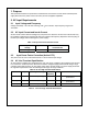
1. Purpose This specification defines the performance characteristics and functions of a 950 watts redundant power supply with Active PFC (Power Factor Correction) and hot swappable capabilities. 2. AC Input Requirements 2.1 Input Voltage and Frequency Voltage (sinusoidal) : 100~240 VAC full range, with 47hz~63hz 2.2 10% tolerance.
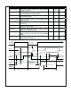
Duration Surge Operating AC Voltage Line Frequency Performance Criteria Continuous 10% Nominal AC Voltage 50/60 Hz No loss of function or performance 0 - ½ AC cycle 30% Mid-point of Nominal AC Voltage 50/60 Hz No loss of function or performance 3. DC Output Specification 3.1 Output Power / Currents Voltage Table 4: Load Range Minimum Load Maximum Load +3.3V 1A 30A + 5V 1A 40A +12V 2A 68A -12V 0A 0 .5 A +5VSB 0.1 3A Notes: Note 1: The +5 & +3.
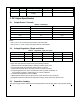
requirements. Table 6: Capacitive Loading Conditions 3.4 Output MIN MAX +3.3V 10 12000 Units uF +5V 10 12000 uF +12V 10 11000 uF -12V 1 350 uF +5VSB 1 350 uF Dynamic Loading The output voltages shall remain within the limits specified in Table-Regulation, ripple and noise for the step loading and within the limits specified in Table-Transient Load Requirement for the capacitive loading.
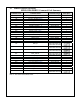
regulation. Tac_on-delay Delay from AC being applied to all output voltages being within regulation. Tvout_holdup Time all output voltage stay within regulation after loss of AC tested at 80% of maximum load. 17 mS Tpwok_holdup Delay from loss of AC deassertion of PWOK tested at 80% of maximum load. 16 mS Tpson_on_delay Delay from PSON# active to output voltage within regulation limits. 5 Tpson_pwok Delay from PSON# deactive to PWOK being deasserted.
3.
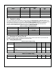
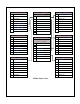
Over Limit STATUS(B1h) STATUS_WORD(79h) 7 Reserved 6 Reserved 5 Reserved 7 6 4 Reserved 3 3V3_VOUT_OV 2 (Upper byte) STATUS_VOUT(7Ah) 7 VOUT_OV_Fault(12V) 6 Reserved 5 Reserved 5 VOUT IOUT Reserved 4 Reserved Reserved Reserved 3 Reserved 5V_VOUT_OV 4 3 2 Reserved 1 3V3_IOUT_OC 2 1 Reserved 0 5V_IOUT_OC 1 FAN Reserved 0 Reserved 0 Reserved Power STATUS(B0h) 7 Reserved 6 Reserved 5 Reserved 4 3 2 Reserved 1 PS_ON 0 AC_OK Power ON Module Status STATUS_FANS_
Status Registers Content Byte Bit Number STATUS_WORD 7 79h Status Bit Name Meaning VOUT 1: Any output voltage fault or warning has occurred; 0: Normal 1: Any output current fault or warning has occurred; 0: Normal 6 IOUT 5 4 3 2 Reserved Reserved Reserved FAN 1 0 7 6 5 Reserved Reserved Reserved Reserved VOUT_OV 4 IOUT_OC 3 2 Reserved Temperature 1 0 Reserved Reserved 7 6 5 4 3 2 1 0 Reserved Reserved Reserved Reserved Power on Module Status PS_ON AC_OK 1: Power OFF; 0: Power ON 1: Not i
STATUS_FANS_1_2 81h 7 6 5 4 3 2 1 0 Fan 1 Fault Reserved Reserved Reserved Reserved Reserved Reserved Reserved 1: Fan speed <300 rpm. 0: Normal 7 6 5 4 3 2 1 0 VOUT_OV_Fault Reserved Reserved Reserved Reserved Reserved Reserved Reserved 1: 12V has an over-voltage fault. 0: Normal IOUT_OC_Fault Reserved Reserved Reserved Reserved Reserved Reserved Reserved 1: 12V has an over-current fault.
2 The power efficiency shall be 78% at ATE test at full load@115Vac input. 4. Protection Circuits Protection circuits inside the power supply shall cause only the power supply’s main outputs to shutdown. If the power supply latches off due to a protection circuit tripping, an AC cycle OFF for 15 sec and a PSON# cycle HIGH for 1 sec must be able to restart the power supply. 4.1 Over Current Protection (OCP) The power supply shall have current limit to prevent the +5V, +3.
5. Environmental Requirements 5.1 Temperature Operating Ambient, normal mode (inlet air): 0°C ~ 4 5°C (32°F~ 113°F) Non-operating Ambient:: -40°C ~ 70°C (-40°F~ 158°F) 5.2 Humidity Operating: 20% ~ 90%RH non-condensing Non-Operating: 5% ~ 95%RH non-condensing 5.3 Altitude Operating: Sea level to 10,000 ft Non Operating: Sea level to 40,000 ft 5.4 Mechanical Shock Non-Operating: 50 G Trapezoidal Wave, 11mS half sin wave. The shock is to be applied in each of the orthogonal axes. 5.
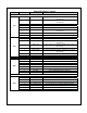
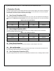
Conducted Voltage Dips and Interruptions Leakage Current 5.7 EN61000-4-11 30%(Voltage Dips) 10 ms 60%(Voltage Dips) 100ms >95%(Voltage Dips) 500ms EN60950-1 3.5mA@240VAC Criteria B Criteria C Criteria C Safety Agency Requirements This power supply is designed to meet the following safety Table 13: Product Safety Product Safety: UL,cUL CB TUV CCC FCC BSMI UL60950-1 IEC60950-1 EN60950-1 CNS14366 6 Reliability 6.
8.