
manual
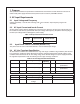
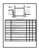

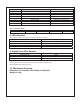

Bit Number Status Bit Name Meaning
7 Reserved Default=0
6 Reserved Default=0
5 Reserved Default=0
4 Reserved Default=0
3 Reserved Default=0
2 Module Status Inserted=0, Not inserted=1
1 PS_ON Status PS_OFF=0, PS_ON=1
0 AC Status AC OK=0, AC Fail=1
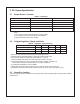
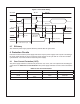
Device address locations
PDB adderss A0/A1 0/0 0/1 1/0 1/1
PSU PMBUS Device B0h B2h B4h B6h
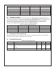
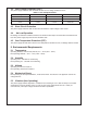
8. LED Indicators
There will be a LED on each power module to indicate power status
Power Supply Status Color
Works Normally Green
Standby (Only +5VSB output) Blinking Green
Power Fail Red
Fan Fail Blinking Red
9. Signals from Wire Harness
Power Supply Status Signal Type
Works Normally High
Power Fail Low
Fan Fail Low
Alarm reset is used to clear power fail status by shorting circuit activities.
Buzzer shall alarm if signal goes low.
10. Mechanical Overview
Dimension: 101.8mm(W) x 83.4mm(H) x 280mm(D)
Weight: 4.8 Kg