
Instruction Manual
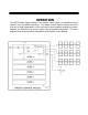
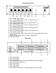


Front Panel Controls
1. Zone 1 Master Level Control
2. Zone 1 Link Indicator (when lit Zone 1 is linked to Zone 2)
3. Zone 2 Mater Level Control
4. Zone 2 Link Indicator (when lit Zone 2 is linked to Zone 3)
5. Zone 3 Master Level Control
6. Zone 3 Link Indicator (when lit Zone 3 is linked to Zone 4)
7. Zone 4 Mater Level Control
8. Zone 4 Link Indicator (when lit Zone 4 is linked to Zone 5)
9. Zone 5 Master Level Control
10. Zone 5 Link Indicator (when lit Zone 5 is linked to Zone 6)
11. Zone 6 Mater Level Control
12. Zone 6 Link Indicator (when lit allow zone 6 to link to another Master Control
Module Zone 1
13. Power LED, illuminates when the power is switched ON
14. Main Power Switch
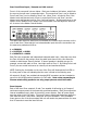
Rear Panel
1. Zone 6 connections
2. Zone 5 connections
3. Zone 4 connections
4. Link Out (allows connection to an additional Master Control Module)
5. Power Inlet for IEC power cord
6. Zone 3 connections
7. Zone 2 connections
8. Zone 1 connections
9. Link In (allows connection to an additional Master Control Module)