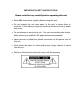
IMPORTANT SAFETY INSTRUCTIONS! Please read this very carefully before operating this unit Read ALL instructions carefully before using this unit. Do not operate this unit near water, in the rain, or where there is moisture. If this warning is ignored a serious electrical shock or death may occur. Do not attempt to service this unit. No user serviceable parts inside. Refer servicing to qualified, ISP approved service personnel.
INTRODUCTION Thank you for your purchase of the ISP Technologies High Definition Distributed System MASTER CONTROL MODULE. This product provides a new level of performance in distributed audio systems allowing greater system flexibility and easy installation of distributed sound. All outputs and control connections are made via Cat5 RJ45 connections making installation of systems faster and easier using the Master Control Module.
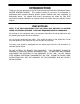
OPERATION The HDDS Master Control Module is the Master control center for distributed sound systems using the HDDS technology. The Master Control Module includes six zones that can be used independently or can be linked to work together allowing the system designer the flexibility to set up any system with the desired configuration. The block diagram below shows the basic configuration of the Master Control Module.
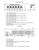
Front Panel Controls 1. Zone 1 Master Level Control 2. Zone 1 Link Indicator (when lit Zone 1 is linked to Zone 2) 3. Zone 2 Mater Level Control 4. Zone 2 Link Indicator (when lit Zone 2 is linked to Zone 3) 5. Zone 3 Master Level Control 6. Zone 3 Link Indicator (when lit Zone 3 is linked to Zone 4) 7. Zone 4 Mater Level Control 8. Zone 4 Link Indicator (when lit Zone 4 is linked to Zone 5) 9. Zone 5 Master Level Control 10. Zone 5 Link Indicator (when lit Zone 5 is linked to Zone 6) 11.
Principles of the Master Control Module operation: Each of the six zones of the Master control Module allow input of a balanced audio signal and a front panel Master Level Control for each zone. As can be seen in the previous block diagram all level control is provided by a voltage controlled amplifier. The VCA output is followed by a differential line driver which drives the outputs A, B and C on the rear panel of the Master Control Module.
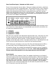
Rear Panel Zone Input / Outputs and Link control Zone 1 of the rear panel is shown below. Each zone includes a link button, which links the zone to the next zone in sequential order. This means that Zone 1 can be linked to Zone 2 and Zone 2 can be linked to Zone 3 etc. When Zone 1 is linked to Zone 2 the Master Level and Remote Level of Zone 1 control both Zone 1 and Zone 2 and the Master Level and Remote Level for Zone 2 will not function.
SPEAKER POWER: The HDDS system distributes low voltage Alternating Current over the Cat5 cable plus high level balanced audio and is capable of greater than 30 watts continuous power per speaker. Each of the three outputs A, B and C are capable of delivering up to 7 amps of output current. With a typical power per speaker of 10 watts each speaker will consume on the order of 400mA, which means that 12 ceiling speakers would require 4,800mA of current.
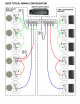
Cat5 Connections The figure below shows the connections for each output A, B and C of each zone. Connections are done via standard Cat5 cables where pins 1 through 8 are connected common to the same pins 1 through 8 at each end. As shown below two wires in the Cable are use for balanced audio and 6 wires are used for power with two providing ground and two for each of two 22VAC power signals fed down the cable.
HDDS MASTER CONTROL MODULE SPECIFICATIONS POWER CONSUMPTION: 10 AMP MAXIMUM @120VAC AUDIO INPUT: Balanced 20k input impedance Pin 1 = GND Pin 2 = Audio + Pin 3 = Audio - OUTPUT PER ZONE: 7 AMP CONTINUOUS 10 AMP PEAK MAX TOTAL OUTPUT CURRENT: 33 AMPS LEVEL CONTROL: INTERNAL VCA CONTROL REMOTE CONTROL LAW: 10VDC – OVDC 1V / 10DB WEIGHT: 18LBS
WARRANTY AND SERVICE The unit, parts and workmanship are fully guaranteed to be free of defects under normal use and service for a period of 3 years from the date of purchase. Any damage resulting from the misuse or the failure to follow the precautions and instructions will void the warranty. In the event that the unit needs to be repaired, please return the unit to ISP Technologies directly.