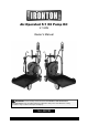
Air-Operated 5:1 Oil Pump Kit 3.7 GPM Owner’s Manual WARNING: Read carefully and understand all ASSEMBLY AND OPERATION INSTRUCTIONS before operating. Failure to follow the safety rules and other basic safety precautions may result in serious personal injury.
Thank you very much for choosing an Ironton™ product! For future reference, please complete the owner’s record below: Serial Number/Lot Date Code: ________________________________ Purchase Date: ____________________________________________ Save the receipt, warranty, and this manual. It is important that you read the entire manual to become familiar with this product before you begin using it. This pump is designed for certain applications only.
Table of Contents Intended Use .......................................................................................................................................... 4 Packaging Contents .............................................................................................................................. 4 Technical Specifications ...................................................................................................................... 4 Important Safety Information .................
Intended Use The Ironton Air-Operated 5:1 Oil Pump Kit is suitable for dispensing oil at medium/high viscosity for mobile installations and fixed systems at long distances. The multi-drum trolley ensures high mobility and high efficiency.
Important Safety Information ⚠WARNING Read and understand all instructions. Failure to follow all instructions may result in serious injury or property damage. The warnings, cautions, and instructions in this manual cannot cover all possible conditions or situations that could occur. Exercise common sense and caution when using this tool. Always be aware of the environment and ensure that the tool is used in a safe and responsible manner.
⚠WARNING PERSONAL SAFETY Stay alert, watch what you are doing, and use common sense when operating the tool. Do not use the tool while you are tired or under the influence of drugs, alcohol, or medication. A moment of inattention while operating the tool may result in serious personal injury. Dress properly. Do not wear loose clothing, dangling objects, or jewelry. Keep your hair, clothing and gloves away from moving parts. Loose clothes, jewelry, or long hair can be caught in moving parts.
Specific Operation Warnings ⚠WARNING To prevent serious injury or property damage, read and understand owner's manual before operating. Wear ANSI Z87.1 compliant goggles and other protective gear while operating. Do not exceed the maximum working air pressure of 115 PSI. Never point the dispenser at people or animals. Do not use the pump near open flames. Do not smoke during this operation. When not in use, disconnect the air supply air to the pump.
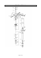
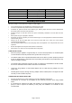
Main Parts of Product Page 8 of 30
Reference Subassembly Quantity 1 2 Air motor cover Air control center 1 1 3 4 5 6 7 8 Air motor shell inside Bracket Bracket Screw Shaft Piston shaft 1 1 1 1 1 1 9 10 11 12 13 14 Piston cover Out cover Side cover Suction tube Slider Gasket 1 1 1 1 1 1 15 16 17 18 19 20 Soft gasket Securing washer Spring circlip Outlet Piston Valve seat 1 1 1 1 1 1 21 22 23 24 25 26 Filter Piston Slider Connecting shell Connect shaft Air center cover 1 1 1 1 1 1 27 28 29 30 31 96 Spring shell Spring Spring
Reference Quantity 213 214 Subassembly U seal Guiding 215 216 O-ring Quick coupling 1 1 1 1 Assembly Instructions When the pump is connected to the compressed air supply: • • • • • • • • • • The compressed air must be filtered to avoid dust into pump. The max compressed air pressure must not exceed 115 psi. To deliver oil, press the knob on the delivery gun; delivery stops when the knob is released but the whole system remains under pressure.
CONNECTION OF OIL DISCHARGE 1. The Oil discharge outlet is a 1/2'' Male. Connect the outlet to the high pressure hose (according to DIN-SAE norms) through the corresponding adapter and terminal. 2. Ensure the gun or corresponding valve is closed. 3. Slowly open the pump's compressed air inlet valve. The pump will start to function, filling the feed circuit with oil. Maintain pressure on the gun until the oil start to come out. The pump is now ready for its usual function.
Digital Installation: Fig. 1 shows a typical installation. The installation shown in Fig. 1 is only a guide. The components shown are typical; however, it is not a complete system design. Contact your distributor for assistance in designing a system to suit your particular needs. Pre-Installation Procedure 1. Relieve the pressure. 1. Close the fluid shut-off valve (item 4 in Fig.1). 2. Ground the hose and reel or console.
New Installation 1. Relieve the pressure. 2. Close the fluid shut-off valve at each dispense position. 3. Make sure the main fluid outlet valve at the pump is closed, the air pressure to the pump motor is adjusted, and the air valve is open. Slowly open main fluid valve. 4. Place the hose end (with no dispense valve connected) into a container for waste oil. Secure the hose in the container so it will not come out during flushing.
Installation of Hose Reel 1) For overhead ceiling mounting: Install reels at least 10 feet above the floor. 2) If the reel you have purchased does not have hose included, you will need to purchase and attach. Refer to Specifications on box to determine appropriate hose size and length. 3) You will need to purchase appropriate hardware for mounting your new reel. a. The reel base has four 0.4” (or 10.5mm) drilled holes for mounting on a suitable flat surface.
Before Each Use ⚠WARNING Inspect before each use; check that all connections are tight and secure. Never use if parts are damaged or broken; replace damaged or broken parts before operating. Disconnect air hose and relieve air pressure before servicing. TIGHTEN all fluid connections securely before each use. High pressure fluid can dislodge a loose coupling or allow high pressure spray to be emitted from the coupling. NEVER use a damaged hose.
Activating the Digital Display Press the RESET key pad to clear the meter before starting a new dispense cycle. This is the best way to activate the meter, because it also clears the quantity of the last dispense cycle. The digital display can also be activated by pressing the MENU key pad or by running fluid through the meter. Calibrating Automatically - Press Reset key for 1 second and Area 1 shows .
Dispensing Procedure Note: Before you begin, make sure you understand how to unlock the trigger. 1. Pull the trigger toward the valve body to open the valve and begin dispensing. 2. Lock the valve open by keeping the trigger squeezed and depressing the trigger lock button. Then release the trigger, releasing your forefinger from the trigger lock last. 3. Pull the trigger toward the valve body to release the trigger lock. The trigger lock disengages. Release the trigger to stop dispensing.
Always disconnect the air supply after use so that oil can't leak out in case one of the pump's components should break. Keep the pump in a dry and cool place out of the reach of children. Pumps are delivered in appropriate cardboard boxes. Packaging material should be properly disposed. Handling and storage of the new pump does not require any special procedures, however after the pump has been used, empty the used oil in the suction tube into an appropriate container.
Troubleshooting Pump Failure The pump continues to operate after the gun trigger has been released. Reduction of the oil delivery or reduced pressure in the oil delivery. Air loss through the air exhaust. Possible Cause Corrective Action There is oil leak at some point of the circuit. Check and tighten connections. Repair the leak. Valve sets (part # 22 and 203, 204, 213, 214) close incorrectly due to dirt or wearing. Have damaged parts replaced. Silencer (209) is dirty.
Failure Possible Cause Corrective Action 1. Take the meter off the dispense system. 2. Take off the protector. 3. Loosen four of the socket head cap screws on the cover of the meter. Leakage from meter. 4. Loosing eight of the hex bolts on the bottom of the meter. O-ring damaged. 5. Take off the seat. 6. Check the O-ring and replace the O-ring if it is damaged. After replacing the O-ring, disassemble the meter and attach it back to the dispense system.
Parts Diagram Page 21 of 30
Trolley Page 22 of 30
Digital Control Valve Page 23 of 30
Hose Reel Parts List Part Number 1 2 3 4 5 6 7 8 9 10 11 12 13 14 15 16 17 18 19 20 21 22 23 24 25 26 27 Part Description Pump Parts List Air motor cover Air control center Air motor shell inside Bracket Bracket Screw Shaft Piston shaft Piston cover Out cover Side cover Suction tube Slider Gasket Soft gasket Securing washer Spring circlip Outlet Piston Valve seat Filter Piston Slider Connecting shell Connect shaft Air center cover Spring shell Page 24 of 30 Quantity 1 1 1 1 1 1 1 1 1 1 1 1 1 1 1 1 1 1 1
Part Number 28 29 30 31 96 97 98 99 100 101 108 200 201 202 203 204 209 212 213 214 215 216 212 213 214 1 2 3 4 5 6 7 8 9 10 11 12 13 14 15 16 17 18 19 20 21 22 23 24 25 26 27 28 Part Description Spring Spring seat Trip shoe guide Press piece Pin Pin Ball Small circlip Ball Screw Nut O-ring O-ring O-ring U-ring O-ring Silencer O-ring U seal Guiding O-ring Quick coupling O-ring U seal Guiding Trolley Parts List Accessories Drum holder support Handle Pump support Hexagon set screw Stopper Accessories support
Part Number 1-1 1-2 1-3 1-4 1-5* 1-6 1-7* 1-8 1-9 1-10* 1-11 1-12 1-13* 2 3-1* 3-2 3-3 3-4 3-5 3-6 3-7 3-8 3-9 3-10 3-11 3-12 3-13* 3-14 3-15 3-16 3-17 3-18 3-19* 3-20* 3-21 4 3-5 MH10001 MH10002 MT10001 MT10002 MT10003 1-5* 1-7* 1-10* 1-13* 3-1* 3-9* 3-13* 3-19* 3-20* Part Description Digital Control Valve Parts List Swivel Handle Trigger lock Trigger O-ring Screw Flat washer Cam Rod Seat Washer Spring Filter Adapter O-ring Meter holder Meter cover Rubber protector Main circuit board Front label Screw Scr
1 2 3 4 5 6 7 8 9 10 11 12 13 14 15 16 17 18 19 20 21 22 23 24 25 26 27 28 29 30 31 32 33 34 35 36 37 38 39 40 41 42 43 44 45 46 47 Hose Reel Parts List Nut Spring washer Washer Bolt Bracket arm Washer Ratchet Washer Lock washer Click pulley Nut Lock washer Washer Shaft Key Guide sub-plate Drum Roller axle Roller Roller Roller axle Guide plate Bolt Base Double bolt Spring core spring Drum Swivel shaft Washer O-ring or seal Washer Not shown Not shown Swivel shaft Bearing cover Ball bearing Bearing washer Wa
Replacement Parts For replacement parts and technical questions, please call Customer Service at 1-800-222-5381. Not all product components are available for replacement. The illustrations provided are a convenient reference to the location and position of parts in the assembly sequence. When ordering parts, the following information will be required: item description, item model number, item serial number/item lot date code, and the replacement part reference number.
Limited Warranty Northern Tool and Equipment Company, Inc. ("We'' or "Us'') warrants to the original purchaser only ("You'' or "Your") that the Ironton product purchased will be free from material defects in both materials and workmanship, normal wear and tear excepted, for a period of 90 days from date of purchase. The foregoing warranty is valid only if the installation and use of the product is strictly in accordance with product instructions.
Distributed by: Northern Tool & Equipment Company, Inc. Burnsville, Minnesota 55306 www.northerntool.