
Product Manual

8
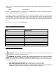
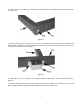
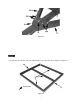
6. Position left tow bar bracket (4L) and right tow bar bracket (4R) on cross members (2) and connect with
M10 x 20 bolt (D) and M10 nylon locknuts (G). See figure 2-2.
Figure 2-2
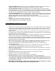
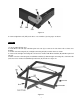
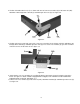
7. Install tow bar (4) with the opening facing up as shown between tow bar brackets. See figure 2-3.
8. Install tow bar pin (9) and lock pin (M).
9. Install M12 x 90 bolt (P) and M12 nylon lock nut (O).
10. Turn assembled frame over.
Figure 2-3
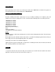
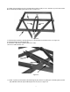
11. Install “T” plate (5) onto tow bar and install wing nut (N). Connect “T” plate (5) to connecting rails (3L) and
(3R) with M10 x 20 bolts (D) and M10 nylon lock nuts (G). See figure 2-4.