
Product Manual

6
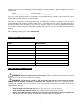
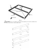
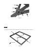
2. Connect front cross member (2) to left frame rail (1FL) with M10 x 20 bolt (D) and M10 nylon lock nut (G).
See figure1-2.
Figure 1-2
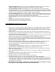
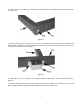
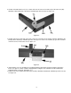
3. Position stake pocket (25) and connect the center cross member (2) to left frame rail (1FL) with M10 x 20
bolt (D), M10 x 30 bolt (C) and M10 nylon lock nuts (G). The center cross member goes in the rear of the
three holes on left frame rail. See figure 1-3.
Figure 1-3
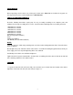
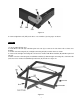
4. Verify that the rear cross member (2) is positioned with the opening the channel facing the hitch. See
figure1-4.
5. Position rotation bracket (25) as shown and connect rear cross member (2) to left frame rail (1FL) with
M10 x 20 bolt (D), M10 x 30 bolt (C) and M10 nylon lock nuts (G). See figure 1-4.