
Product Manual

20
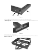
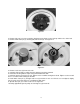
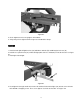
Figure 9-2
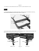
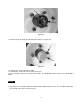
5. Unroll the wiring harness.
6. Position harness so that the harness connector is approximately 18 inches beyond the coupler.
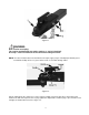
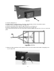
7. Route the harness through the tow bar. See figure 9-3.
8. Route the green/brown wires down the right side frame rail. See figure 9-3.
9. Route the yellow/brown wires down the left side frame rail. See figure 9-3.
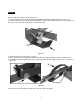
10. Be sure to leave 4 inches of excess wire at the end of the tow bar and 16 inches of excess at the fold
points.
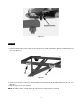
Figure 9-3
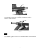
11. Attach the white ground wire to the small hole on the left side of tow bar with a 4mm self-tapping screw
(J). See figure 9-4.