
Integrated Grounding System Installation Manual


Page 2
| ironridge.com | (800) 227-9523
2013 v1.1 support@
Rails with Integrated Grounding
Installation Manual
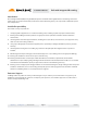
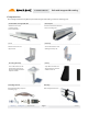
Tools Required For Assembly
Hex Head Size Component
5/16” #10 Hardware and #12 Self-drilling/tapping screws
7/16” 1/4” Hardware (Clamps)
9/16” 3/8” Hardware (L-feet)
Torque Values
Bolt Size Required Torque Value
#10 32 in-lbs Dry (27 in-lbs Lubricated)
#12 84 in-lbs Dry (73 in-lbs Lubricated)
1/4-20 84 in-lbs Dry (73 in-lbs Lubricated)
1/4-20 (End Clamps) 65 in-lbs Dry (55 in-lbs Lubricated)
3/8-16 236 in-lbs (201 in-lbs Lubricated)
Use the following torque values in this assembly.
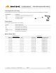
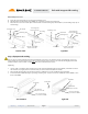
Module Clamp Table
Millimeters Inches End Clamp Grounding Mid Clamp
31.0 - 32.5 1.22 - 1.28 29-7000-125 RS-GD-MCL-200
33.3 - 34.8 1.31 - 1.37 29-7000-134 RS-GD-MCL-200
34.8 - 36.8 1.37 - 1.45 29-7000-224 RS-GD-MCL-225
39.0 - 41.0 1.53 - 1.61 29-7000-157 RS-GD-MCL-225
41.1 - 42.7 1.62 - 1.68 29-7000-165 RS-GD-MCL-250
42.7 - 44.2 1.68 - 1.74 29-7000-171 RS-GD-MCL-250
45.0 - 47.0 1.77 - 1.85 29-7000-214 RS-GD-MCL-250
46.7 - 48.3 1.84 - 1.90 29-7000-187 RS-GD-MCL-275
49.0 - 51.1 1.93 - 2.01 29-7000-204 RS-GD-MCL-275
57.4 - 58.9 2.26 - 2.32 29-7000-230 Unsupported
Module Thickness
Part Numbers
Torque wrenches are required to assemble the rails. The sockets will need to support the following size hex heads: