
Install Manual

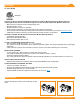

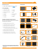
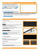
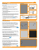
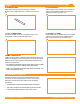
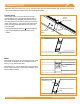
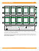
Table Of Contents

©
2021 IRONRIDGE, INC. VERSION 3.3 FLUSH MOUNT INSTALLATION MANUAL - 8
EXPANSION JOINTS
BOSS
Insert BOSS into rst Rail up to the Alignment Circle, Slide
second Rail over BOSS to the second Alignment Circle,
leaving a 1" gap between the Rails.
There must be a 1" of space between the edge of the Rail
and the edge of the panel to allow proper installation of the
UFO and Stopper Sleeve.
A A
B B
C C
D D
E E
F F
8
8
7
7
6
6
5
5
4
4
3
3
2
2
1
1
No Modules Over Gap
One Bonding Strap Per Break In
Array
A A
B B
C C
D D
E E
F F
8
8
7
7
6
6
5
5
4
4
3
3
2
2
1
1
No Modules Over Gap
No Bonding Strap required for
BOSS
Fully Seat Tek
Screws
Insert Splice 6" Into
Rail
Torque to
80 in-lbs
3/8" from Rail End
1" Gap
Expansion Joints are required every 100' of continuous rail to allow for thermal expansion and contraction of the system.
➢ Do not install modules over expansion joints, either Classic Splice or BOSS.
Classic Splice
Insert Classic Splice 6" into rst rail and secure with
two self-drilling screws, spacing them approximately 1”
apart and tightening to 20 in-lbs. Assemble and secure
Grounding Strap 3/8" from rail end. Slide second rail over
Classic Splice leaving 1" gap between rails. Attach other
end of Grounding Strap with hardware and torque hex
nuts to 80 in-lbs.
➢ Remaining Bonded Splice screws are not used with Expansion.
➢ Only one Grounding Strap is required per break in row of
modules.
1" Gap Alignment
Circles