FLUSH MOUNT INSTALLATION MANUAL INSTALLATION MANUAL © 2021 IRONRIDGE, INC. VERSION 3.
Contents DISCLAIMER 1 RATINGS 2 MARKINGS 2 ATTACHMENTS 3 COMPONENTS 4 1. ATTACH BASES 5 2. PLACE RAILS 5 3. SECURE LUGS 6 4.
RATINGS UL 2703 LISTED #5003807 Conforms to STD UL 2703 (2015) Standard for Safety First Edition: Mounting Systems, Mounting Devices, Clamping/ Retention Devices, and Ground Lugs for Use with Flat-Plate Photovoltaic Modules and Panels • Max Overcurrent Protective Device (OCPD) Rating: 40A • Max Module Size: 30.
ATTACHMENTS PRE-INSTALLATION ATTACHMENTS ☐ Verify module compatibility. See Page 21 for info.
COMPONENTS COMPONENTS PRE-INSTALLATION ☐ Verify module compatibility. See Page 21 for info.
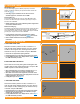
1. PLACE ATTACHMENTS The general installation method for attachments is to locate a rafter, drill a pilot hole and install the attachment. For composition roof attachments installation instructions refer to page 10. For tile roof attachments refer to page 12. For low slope roof attachments refer to page 14. When using approved third party attachments, refer to manufacturer's install instructions.
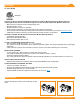
3. SECURE LUGS Grounding Lugs Rail Grounding Lug Only one Grounding Lug (Rail or Module) required per continuous subarray, regardless of subarray size (Unless frameless modules are used, see Page 20). Terminal Screw (20 in-lbs) ➢ Grounding Lugs are intended to for use with one solid or stranded copper wire, conductor size 10-4 AWG. Rail Grounding Lug Insert T-bolt in Top Rail slot and torque Hex Nut to 80 in-lbs. Install a minimum 10 AWG solid copper or stranded grounding wire.
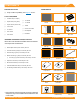
CAMO A. SLIDE INTO RAIL Slide CAMO into rail channel far enough to clear the module frame. CAMO requires 6" of clearance from end of rail. A 6" Cle ara B. PLACE MODULE Place module on rails (module cells not shown for clarity). When installing CAMO the module can overhang the rail no more than 1/4". B nc e C. PULL TOWARDS END Pull CAMO towards rail ends, at 45 degree angle, so the bonding bolt contacts the module flange edge. C D.
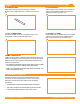
EXPANSION JOINTS Expansion Joints are required every 100' of continuous rail to allow for thermal expansion and contraction of the system. ➢ Do not install modules over expansion joints, either Classic Splice or BOSS. Classic Splice Insert Classic Splice 6" into first rail and secure with two self-drilling screws, spacing them approximately 1” apart and tightening to 20 in-lbs. Assemble and secure Grounding Strap 3/8" from rail end. Slide second rail over Classic Splice leaving 1" gap between rails.
End Caps (Optional) ELECTRICAL DIAGRAM UFO or UFO or CAMO CAMO Rail Grounding Lug* * Grounding Lug Module Grounding Lug* Bonded Splice (Rail Connection) Fault Current Ground Path Minimum 10 AWG * Copper Wire 8" Bonding Jumper (Alternative row to row bond)** *One Module Grounding Lug or Rail Grounding lug is required per row of a system. ** The use of the 8" Bonding Jumper eliminates the need for row to row bonding. A minimum of one grounding lug per continuous array is required for earth ground.
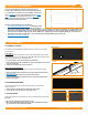
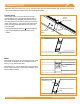
COMPOSITION SHINGLE FLASHFOOT2 Locate roof rafters and mark locations on roof. Drill 1/4" pilot holes perpendicular to the roof and back fill with roofing manufacturers' approved sealant. Slide flashing between 1st and 2nd course of shingles, ensuring both that the flashing reaches under the 3rd shingle course and doesn't overhang the downhill shingle course. Line up with pilot hole and insert supplied lag bolt with washer through flashing. With a 7/16" Socket fully seat lag bolt.
COMPOSITION SHINGLE QM L-MOUNT Locate roof rafters and mark locations on roof. Drill 7/32”(Lag) or 1/8"(ST) pilot holes perpendicular to the roof and back fill with roofing manufacturers' approved sealant. Slide flashing between 1st and 2nd course of shingles, ensuring both that the flashing reaches under the 3rd shingle course and doesn't overhang the downhill shingle course. Place L-foot on flute and rotate into desired position. Prepare lag bolt or structural screw with sealing washer.
TILE KNOCKOUT TILE Remove tile and mark rafter. Use base as guide to drill 1/4” pilot hole and fill with roofing manufacturer’s approved sealant. Insert lag bolt with bonded washer through base and drive until fully seated. Insert Tile Replacement Flashing, lower onto base and apply pressure over the threaded post until it dimples the flashing. Place L-Foot over dimple and tap with hammer to punch threaded post through the flashing. Ensure punched pieces of flashing are cleared away.
TILE ALL TILE HOOK Remove tile and mark rafter. Position base over rafter, adjust arm if necessary and torque hardware to 132 in-lbs (11 ft-lbs). Use base as guide to drill 1/4" pilot holes, back fill with roofing manufacturer’s approved sealant, then insert lag bolts and tighten until fully seated. Replace tiles and notch as necessary to ensure proper fit. Attach rails to either side of slot using Bonding Hardware and torque to 250 in-lbs (21-ft-lbs).
TILE QM QBASE UNIVERSAL TILE MOUNT Remove tile and mark rafter. Measure up 6 5/8" from bottom of tiles and mark horizontally. Align QBase over rafter center and drill two 7/32" pilot holes, back fill with roofing manufacturers' approved sealant. Place grade-8 Cap Screw under QBase, lag QBase into rafter location. Install Sub-flashing, waterproof at underlayment level according to roofing manufacturers' instructions and the Tile Roofing Industry Alliance guidelines.
LOW SLOPE ROOFS FLAT ROOF ATTACHMENT Flat Roof Attachment can be used with an L-foot for flush mounting modules on low sloped roofs. Mark locations for Flat Roof Attachment. Screws should be installed symmetrically to each other. If using a membrane flashing, remove the silicone washer's protective liner prior to attaching the membrane. Attach L-foot with washers and 3/8” hardware torqued to 250 in-lbs (21 ft-lbs). Seal attachment and/or membrane per roofing manufacturer’s requirements.
CONDUIT End CapsPENETRATION (Optional) FLASHINGS QM CONDUIT PENETRATION FLASHING - COMP SHINGLE Mark a drill point so that the flashing reaches up to the 3rd shingle course. Drill your conduit hole next to the rafter so you can secure the conduit below the roof surface. Cut shingle and remove nails as needed to center the drilled hole and flashing hole. Apply roofing manufacturer's approved sealant on the underside of the flashing in a Upside down U and to top of flashing.
CONDUIT MOUNT QM CONDUIT MOUNT - COMPOSITION SHINGLE Place conduit mounts along path of conduit. Lift shingle above mount location and insert flashing into position. Mark center for drilling, remove flashing and drill pilot hole with 1/8" bit. Clean area, fill hole with roofing manufacturer's approved sealant. Lift shingle and slide Conduit Mount into place. Prepare the lag bolt with sealing washer and pipe clamp (not included).
END CAPS End Caps add a completed look and keep debris and pests from collecting inside rail. Firmly press End Cap onto rail end. ➢ End Caps come in sets of left and right. Check that the proper amount of each has been provided. WIRE CLIPS Wire Clips offer a simple wire management solution. Press Clip into Slot Snap Clip Closed Firmly press Wire Clip into top rail slot. Run electrical wire through open clip. Snap closed once all wires have been placed.
MICROINVERTER KITS Use IronRidge's Microinverter Kit to bond compatible microinverters and power optimizers to the racking system. Insert Microinverter Kit T-bolt into top rail slot. Place compatible microinverter or power optimizer into position and tighten hex nut to 80 in-lbs.
SYSTEMS USING MICROSTORAGE PRODUCTS PHAZR Use IronRidge's Microinverter Kit to bond compatible microstroage devices to the racking system. Insert Microinverter Kit T-bolt into top rail slot. Place compatible microstorage into position and tighten hex nut to 80 in-lbs. COMPATIBLE PRODUCTS Microinverter Kit (80 in-lbs) PHAZR PHAZR Devices PHAZR-X, where X is 6-12.
MODULE COMPATIBILITY The Flush Mount System may be used to ground and/or mount a PV module complying with UL 2703 only when the specific module has been evaluated for grounding and/or mounting in compliance with the included instructions. Unless otherwise noted, “xxx” refers to the module power rating and both black and silver frames are included in the certification.
MODULE COMPATIBILITY Ecosolargy Ecosolargy modules with 35, 40, and 50 mm frames ECOxxxYzzA-bbD Where “Y” can be A, H, S, or T; “zz” can be 125 or 156; “A” can be M or P; “bb” can be 60 or 72; and “D” can be blank or B ET Solar ET Solar modules with 30, 35, 40, and 50 mm frames ET-YZZZxxxAA Where "Y" can be P, L, or M; "ZZZ" can be 660, 660BH, 672, 672BH, 754BH, 766BH, 772BH; and "AA" can be GL, TB, TW, WB, WW, BB, WBG, WWG, WBAC, WBCO, WWCO, WWBCO or BBAC Flex Flex modules with 35, 40, and 50 mm frame
MODULE COMPATIBILITY JA Solar JA Solar modules with 30, 35, 40 and 45 mm frames JAyyzz-bbww-xxx/aa Where “yy” can be M, P, M6 or P6; “zz” can be blank, (K), (L), (R), (V), (BK), (FA), (TG), (FA)(R), (L)(BK), (L) (TG), (R)(BK), (R)(TG), (V)(BK), (BK)(TG), or (L)(BK)(TG); “bb” can be 48, 60, 66, 72 or 78; "ww" can be D09, D10, D20, D30, S01, S02, S03, S06, S09, S10, S12, S20 or S30; and “aa” can be BP, MB, MR, SI, SC, PR, 3BB, 4BB, 4BB/RE, 5BB Jinko Jinko modules with 35 and 40 mm frames JKMYxxxZZ-aa Where
MODULE COMPATIBILITY Recom Recom modules with 35 and 40 mm frames RCM-xxx-6yy Where “yy” can be MA, MB, ME or MF REC Solar REC modules with 30, 38 and 45 mm frames RECxxxYYZZ Where “YY” can be AA, M, NP, NP2, PE, PE72, TP, TP2, TP2M, TP2SM, TP2S, TP3M or TP4; and “ZZ” can be blank, Black, BLK, BLK2, SLV, 72, or Pure Renesola ReneSola modules with 35, 40 and 50 mm frames AAxxxY-ZZ Where "AA" can be SPM(SLP) or JC; "Y" can be blank, F, M or S; and "ZZ" can be blank, Ab, Ab-b, Abh, Abh-b, Abv, Abv-b, Bb,
Module Compatibility SunEdison SunEdison Modules with 35, 40 & 50 mm frames SE-YxxxZABCDE Where "Y" can be B, F, H, P, R, or Z; "Z" can be 0 or 4; "A" can be B,C,D,E,H,I,J,K,L,M, or N ; "B" can be B or W; "C" can be A or C; "D" can be 3, 7, 8, or 9; and "E" can be 0, 1 or 2 Suniva Suniva modules with 35, 38, 40, 46, and 50 mm frames OPTxxx-AA-B-YYY-Z MVXxxx-AA-B-YYY-Z Where "AA" is either 60 or 72; "B" is either 4 or 5; "YYY" is either 100,101,700,1B0, or 1B1; and "Z" is blank or B Sunpower Sunpower st
Module Compatibility FRAMELESS MODULE LIST MAKE MODELS Astronergy Solar Astronergy frameless modules CHSM6610P(DG)-xxx Canadian Solar Canadian Solar frameless modules CSbY-xxx-Z Where “b” can be 3 or 6; “Y” is K, P, U, or X; and “Z” can be M-FG, MS-FG, P-FG, MB-FG, or PB-FG Heliene Heliene frameless modules YYZZxxxA Where "YY" can be72; "ZZ" can be M; and "A" can be GH Jinko Jinko frameless modules JKMxxxPP-DV Prism Solar Prism Solar frameless modules BZYY-xxxAAA Where "Z" can be i or N; "YY" can