Installation Manual Roof Mounting System Standard (XRS) and Light (XRL) Rails with Integrated Grounding *ETL Listed Per UL2703 2013 Edition v1.1 A complete manual for the installation of IronRidge’s rail systems with integrated grounding.
Installation Manual Rails with Integrated Grounding This Installation Manual was created to assist the assembly of the IronRidge Standard (XRS) and Light (XRL) Rail Mounting Systems with Integrated Grounding.
Installation Manual Rails with Integrated Grounding Introduction The IronRidge Standard (XRS) and Light (XRL) Rail Systems are flexible and straightforward roof mounting solutions for a wide variety of solar photovoltaic (PV) needs. Due to their modular design, they can easily handle a multitude of panel sizes and quantities. Installer Responsibility The installer is solely responsible for: I.
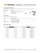
Rails with Integrated Grounding Installation Manual Tools Required For Assembly Torque wrenches are required to assemble the rails. The sockets will need to support the following size hex heads: Hex Head Size Component 5/16” #10 Hardware and #12 Self-drilling/tapping screws 7/16” 1/4” Hardware (Clamps) 9/16” 3/8” Hardware (L-feet) Torque Values Use the following torque values in this assembly.
Installation Manual Rails with Integrated Grounding Component List The IronRidge Standard and Light Rail System with Integrated Grounding contains the following parts: Standard (XRS) and Light (XRL) Rail Internal Splice Attaches to L-foot and provides support for the PV modules. Provides a structural connection when connecting rails. L-Foot End Clamp Attaches to the roof and supports rails. Secures PV modules to rails utilizing the rail top slot.
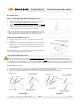
Rails with Integrated Grounding Installation Manual Assembly Steps Step 1. Install Applicable Roof Flashing and L-feet A. B. Determine the appropriate flashing required for your roof type and project. Install flashing per manufacturer’s requirements. Mount all the L-feet to the roof in the desired locations using a minimum 5/16” x 3” long Lag Bolt. The 5/16” Lag Bolt attached to a structural roof member such as a rafter.
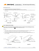
Installation Manual Rails with Integrated Grounding Rail to Rail Expansion Joint A. B. C. Insert splice into first rail then secure splice with self-drilling screw. Attach hardware and Grounding Strap (9AWG) one (1) inch from end of rail as shown below. Next, slide the second rail over the splice and attach other end of Grounding Strap with hardware. (Use Grounding Strap only on rails with lugs.
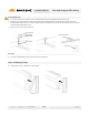
Installation Manual Rails with Integrated Grounding Wiley Grounding Lug (WEEB-6.7) 1. 2. Install grounding lug per manufacturer’s recommendations as shown below (same for both Light and Standard Rails). Install minimum 6-10AWG solid copper grounding conducting wire. 1/4” Hex Nut Torque to 10 ft-lbs 1/4” Lock Washer 1/4” Flat Washer 1/4” Hex Bolt Torque to 7 ft-lbs Weeb 1/4” Hex Bolt Step 5. Installing Modules End Clamp A. B. C. Place the first PV module in position on the rails.
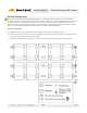
Installation Manual Rails with Integrated Grounding Grounding Mid Clamp D. E. F. Once the first PV module is in place, loosely assemble hardware and Grounding Mid Clamp as shown below. Next, slide second PV module into position underneath the Grounding Mid Clamp and secure with hardware. Ensure the Grounding Mid Clamp teeth are in contact with both of the PV module frames and the T-Bolt is properly aligned in track. T-Bolt indent should be perpendicular to rail. Repeat steps for other clamp and modules.
Installation Manual Rails with Integrated Grounding Electrical Considerations Note: IronRidge Standard (XRS) and Light (XRL) Rail Mounting Systems with Integrated Grounding must be used with UL1703 listed PV modules and must be installed per PV module manufacturer’s installation instructions. All electrical installation and procedures should be conducted by skilled, licensed and bonded electricians or solar contractor.
Installation Manual Rails with Integrated Grounding Warranty Information Effective for IronRidge, Inc.