
UFO Tilt Mount Installation Manual
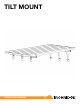
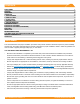
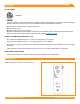
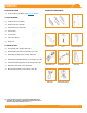

Table Of Contents

CONTENTS
TILT MOUNT INSTALLATION MANUAL - 1©
2016 IRONRIDGE, INC. VERSION 1.10
DISCLAIMER 1
RATINGS 2
MARKINGS 2
CHECKLIST 3
1. ATTACH BASES 4
2. ADD TILT LEGS 4
3. PLACE RAILS 5
4. SECURE LUGS 5
5. SECURE MODULES 6
EXPANSION JOINTS 7
ELECTRICAL DIAGRAM 7
ELECTRICAL DIAGRAM (CONTINUED) 8
END CAPS 8
WIRE CLIPS 8
MICROINVERTER KITS 9
SYSTEMS USING ENPHASE MICROINVERTERS 9
MODULE COMPATIBILITY 10
WARRANTY 11
This manual describes the proper installation procedures and provides minimum standards required for product reliability
and warranty. Thoroughly understanding this manual is imperative to proper installation; failure to follow the guidelines set
forth can result in property damage, bodily injury, or even death.
IT IS THE INSTALLER’S RESPONSIBILITY TO:
• Ensure that the installation is completed by a licensed solar professional. All electrical installation and procedures
should be conducted by a licensed and bonded electrician or solar contractor. Routine maintenance of a module or
panel shall not involve breaking or disturbing the bonding path of the system.
• Comply with all applicable local or national building and re codes, including any that may supersede this manual.
• Ensure all products are appropriate for the installation, environment, and array under the site’s loading conditions.
• Use only IronRidge parts or parts recommended by IronRidge; substituting parts may void any applicable warranty.
• Review the Design Assistant, Engineering Design Guide, and Certication Letters to conrm design specications.
• Refer to IronRidge's Structural Certication Letters for state specic design conditions including allowable rail spans,
cantilever length, and splice location requirements.
• Comply with all applicable re codes including, but not limited to, keeping walkways clear and avoiding obstacles.
• Ensure provided information is accurate. Issues resulting from inaccurate information are the installers’ responsibility.
• Ensure bare copper grounding wire does not contact aluminum and zinc-plated steel components, to prevent risk of
galvanic corrosion.
• If loose components or loose fasteners are found during periodic inspection, re-tighten immediately. If corrosion is
found, replace affected components immediately.
• Provide an appropriate method of direct-to-earth grounding according to the latest edition of the National Electrical
Code, including NEC 250: Grounding and Bonding, and NEC 690: Solar Photovoltaic Systems.
• Disconnect AC power before servicing or removing microinverters and power optimizers.
DISCLAIMER