
Installation Guide
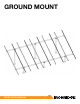

GROUND MOUNT INSTALLATION MANUAL - 5©
2016 IRONRIDGE, INC. VERSION 1.10
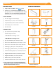
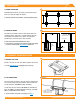
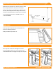
3. PLACE RAILS
A. ATTACH HARDWARE
On the ground, attach Rail Connector brackets to rail by
sliding 3/8”-16 bonding bolts into side slot. Space out to
match pier spacing. With brackets in place, nger tighten
ange nuts onto bolts.
í Tape ends of rail, to keep bolts from sliding out while moving.
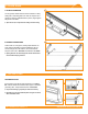
B. FASTEN CONNECTORS
Center rails on cross pipes, leaving equal distance on
ends. Secure with Rail Connector hardware: 3/8”-16
U-bolts, ange nuts, at washers, and lock washers.
Torque U-bolt nuts to 60 in-lbs and bracket to 21 ft-lbs.
í Spacing between rails should align with module manufacturer
recommended clamping locations.
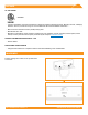
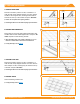
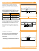
GROUNDING LUGS
Insert T-bolt in top rail slot and torque hex nut to 80 in-
lbs. Install a minimum 10 AWG solid copper or stranded
grounding wire. Torque terminal screw to 20 in-lbs.
í Only one Grounding Lug required per continuous subarray.
í Grounding Lugs can be installed anywhere along the rail and in
either orientation shown.
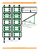
4. SECURE LUGS
A
B
U-Bolt
60 in-lbs
Bracket
21 ft-lbs
Hex Nut
(84 in-lbs)
Terminal Screw
(20 in-lbs)
Hex Nut
(80 in-lbs)