
Installation Guide
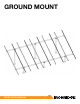

GROUND MOUNT INSTALLATION MANUAL - 4©
2016 IRONRIDGE, INC. VERSION 1.10
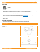
1. BUILD BASE
A. MARK LOCATIONS
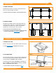
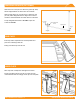
Establish pier locations. Once grid of pier locations has
been set, verify all angles are square.
í Spacing varies with load conditions. Consult engineering specs.
B. POSITION PIERS
Excavate the foundation holes. Insert vertical piers into
foundation holes, and pour in concrete mixture. Ensure
vertical piers are plumb, level, square, and placed in
parallel rows. Level the tops so they are even.
í Brace piers until concrete foundation has cured.
í In some cases, cross bracing is required to provide extra support
for piers. If required, install Diagonal Braces at this time.
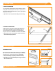
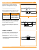
A. MOUNT TOP CAPS
Mount a Top Cap on each pier. Wait to tighten set screws.
í If using Diagonal Braces, install them prior to Top Caps.
B. LAY CROSS PIPE
Set cross pipes or tubing in Top Cap grooves. Attach with
3/8” U-bolts, ange nuts, at washers, and lock washers.
Torque U-bolts to 15 ft-lbs and align assembly.
Torque Top Cap set screws to 20 ft-lbs for Schedule 40
Pipe, 11 ft-lbs for 2” Allied Mechanical Tubing, and 16 ft-
lbs for 3” Allied Mechanical Tubing.
í To join more than one section of cross pipe, see
Page 9.
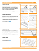
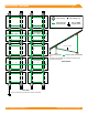
2. CONNECT SUBSTRUCTURE
A
B
A
B
Level Tops
Vertical Pier
(Schedule 40 Pipe)
Level Ground
90°
U-Bolt
15 ft-lbs
Set Screws
Schedule 40 Pipe: 20 ft-lbs
2” Allied Tubing: 11 ft-lbs
3” Allied Tubing: 16 ft-lbs
1/3 Depth
Concrete
Foundation
Depth