
Installation Guide
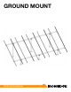

GROUND MOUNT INSTALLATION MANUAL - 3©
2016 IRONRIDGE, INC. VERSION 1.10
CHECKLIST
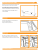
IRONRIDGE COMPONENTS
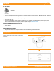
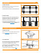
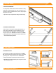
XR1000 Rail Rail Connector
Top Cap UFO
Diagonal Brace
End Cap Wire Clip
Stopper Sleeve
PRE-INSTALLATION
☐ Verify module compatibility. See Page 11 for info.
☐ Purchase 2” or 3” ASTM A53 Grade B Schedule 40
Pipe, galvanized to a min of ASTM A653 G90 or ASTM
A123 G35, or 2” or 3” Allied Mechanical Tubing with
Gatorshield or FlowCoat Zinc coating (ASTM A1057).
TOOLS REQUIRED
☐ Post Hole Digger or Powered Auger
☐ Socket Drive (7/16”, 9/16”, and 1/2” Sockets)
☐ Torque Wrenches (0-240 in-lbs and 10-40 ft-lbs)
☐ Transit, String Line, or Laser Level
☐ 3/8” Allen Head
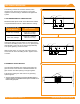
TORQUE VALUES
☐ Top Cap Set Screws (3/8” Allen Head)
Schedule 40 Pipe: 20 ft-lbs
2” Allied Mechanical Tubing: 11 ft-lbs
3” Allied Mechanical Tubing: 16 ft-lbs
☐ Top Cap U-Bolt Nuts (9/16” Socket): 15 ft-lbs
☐ Rail Connector Bracket Nuts (9/16” Socket): 21 ft-lbs
☐ Rail Connector U-Bolt Nuts (9/16” Socket): 60 in-lbs
☐ Grounding Lug Nuts (7/16” Socket): 80 in-lbs
☐ Grounding Lug Terminal Screws (7/16 Socket): 20 in-lbs
☐ Universal Fastening Objects (7/16” Socket): 80 in-lbs
☐ Diagonal Brace Set Screws (1/2” Socket): 15 ft-lbs
☐ Diagonal Brace Bolts (1/2” Socket): 40 ft-lbs
☐ MLPE Kit Nuts (7/16” Socket): 80 in-lbs
☐ Frameless Module Kit Nuts (7/16” Socket): 80 in-lbs
í If using previous version of: Integrated Grounding Mid Clamps,
Grounding Lug, End Clamps, and Expansion Joints please refer to
Alternate Components Addendum version 1.0
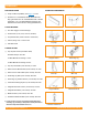
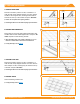
Grounding Lug
Microinverter Kit
Frameless Module Kit