
Installation Guide
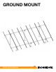

GROUND MOUNT INSTALLATION MANUAL - 9©
2016 IRONRIDGE, INC. VERSION 1.10
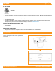
SPLICING CROSS PIPE
The following instructions should be followed, when
required, to join more than one section of cross pipe
together to ensure bonding is maintained throughout the
system.
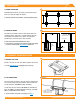
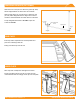
A. ALLIED MECHANICAL TUBING SPLICES
Mechanical tube splices shown in the table below shall be
of equivalent Allied Flowcoat or Gatorshield zinc coating.
Insert splice tube 6” into rst section of cross pipe and se-
cure with 2 self-drilling screws (1/4”-14 x ¾”), spacing them
approximately 1.25” from end of pipe and approximately
3.50” apart, tightening screws to 9 ft-lbs.
Slide second section of cross pipe over splice tube and
secure with two more self-drilling screws. Tighten screws
to 9 ft-lbs.
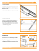
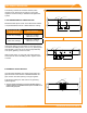
B. SCHEDULE 40 PIPE SPLICES
Use galvanized threaded pipe couplings that match the
pipe size used for the structure. Threaded Schedule 40
pipe must be used when splicing cross pipe together.
Fully thread coupling onto both sections of pipe being
spliced together.
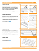
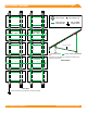
í To ensure structural integrity of cross pipes,mechanical tube or
coupling splices are not permitted in end spans or in middle 1/3 of
interior cross pipe spans.
Mechanical Tube Size
of the Structure
Splice Tube Size
2.375” OD, 12 Gauge
2.000” OD, 9 Gauge,
Minimum 12” Long
3.500” OD, 8 Gauge
3.000” OD, 12 Gauge,
Minimum 12” Long
12.0"
6.0"
1.25"
3.50"
Cross Pipe
Internal Splice
9 ft-lbs
TYP
Cross Pipe
Threaded Coupling
12.0"
6.0"
1.25"
3.50"
Cross Pipe
Internal Splice
9 ft-lbs
TYP
Cross Pipe
A
B