
T-Bolt L-Foot V2 Bonding Hardware Kit Single Manual

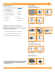
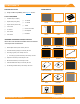
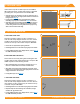

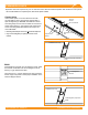
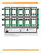
Table Of Contents

©
2020 IRONRIDGE, INC. VERSION 3.0 FLUSH MOUNT INSTALLATION MANUAL - 6
3. SECURE LUGS
Insert T-bolt in top rail slot and torque hex nut to 80 in-
lbs. Install a minimum 10 AWG solid copper or stranded
grounding wire. Torque terminal screw to 20 in-lbs.
➢ Ground Lugs are only needed on one rail per continuous row of
modules, regardless of row length (unless frameless modules are
being used, see Page 20).
➢ If using Enphase microinverters or Sunpower AC modules,
Grounding Lugs may not be needed. See Page 9 for more info.
➢ Grounding Lugs can be installed anywhere along the rail and in
either orientation shown. If installing lug underneath modules
in areas with ground snow loads greater than 40 psf, place lug
within 4 inches module frame edge.
4. SECURE MODULES
A. SECURE FIRST END
Place rst module in position on rails, a minimum of 1”
from rail ends. Snap Stopper Sleeves onto UFO. Fasten
module to rail using the UFO, ensuring that the UFO is
hooked over the top of the module. Torque to 80 in-lbs.
➢ Ensure rails are square before placing modules.
➢ Hold Stopper Sleeves on end while torquing to prevent rotation.
➢ If using CAMO instead of UFO + Stopper Sleeve, refer to Page 19
for CAMO installation procedure.
B. SECURE NEXT MODULES
Place UFO into each rail, placing them ush against rst
module. Slide second module against UFO. Torque to 80
in-lbs. Repeat for each following module.
➢ When reinstalling UFO, move modules a minimum of 1/16" so
UFOs are in contact with a new section of module frame.
➢ When UFOs are loosened and re-tightened, ensure UFO T-bolt
bottoms out in rail channel before re-torquing UFO to achieve full
engagement between T-bolt and rail.
➢ If using Wire Clips, refer to Page 18.
C. SECURE LAST END
Place last module in position on rails, a minimum of 1”
from rail ends. Snap Stopper Sleeves onto UFO. Secure
UFO Clamps on rails, ensuring they are hooked over top
of module. Torque to 80 in-lbs.
➢ Hold Stopper Sleeves on end while torquing to prevent rotation.
➢ Repeat all steps for each following row of modules, leaving a
minimum 3/8" gap between rows.
➢ If using CAMO instead of UFO + Stopper Sleeve, refer to Page 6
for CAMO installation procedure.
A
B
Hex Nut
(84 in-lbs)
Terminal Screw
(20 in-lbs)
C
Hex Nut
(80 in-lbs)
1" From
Rail End
UFO
(80 in-lbs)
Stopper
Sleeve
UFO
(80 in-lbs)
UFO
(80 in-lbs)
Use with one solid or stranded copper
wire, conductor size 10-4AWG.