Inversion Table OWNER’S MANUAL Item #5503
TABLE OF CONTENTS SERVICE ------------------------------------------------------------------------- 2 IMPORTANT LABELS -------------------------------------------------------- 3 IMPORTANT SAFETY INSTRUCTIONS -------------------------------- 4 PART DRAWING --------------------------------------------------------------- 5 PART LIST ----------------------------------------------------------------------- 6 INCLUDED HARDWARE & TOOLS -------------------------------------- 7 ASSEMBLY -----------------------------
SERVICE IMPORTANT: FOR NORTH AMERICA ONLY To request product service and order replacement parts, please call our customer service department at: 1-866-924-1688 Monday through Friday, 8:00 AM-5:00 PM Pacific Standard Time, or email us at: service@paradigmhw.com Please visit our website at www.paradigmhw.com.
IMPORTANT LABELS 3
IMPORTANT SAFETY INSTRUCTIONS This inversion table was designed and built for optimum safety. However, certain precautions apply whenever you operate the exercise equipment. Be sure to read the entire manual before assembling and operating this equipment. Also, please note the following safety instructions: 1. Consult your physician or other health care professionals before using the inversion table. 2. Always wear proper exercise apparel when using the equipment. 3.
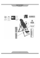
PART DRAWING 5
PART LIST No. Description Qty No. Description Qty 001 Backrest (#5503) 1 026 Ring Pin Ø8x63.5mm 1 002 Backrest Frame 1 027 Hexagon Socket Head Cap Bolt M8x62mm 2 003 Adjustable Boom 1 028 Hexagon Socket Head Cap Bolt M8x20mm 6 004 Foot Bar 1 029 Plastic Washers 4 005 Adjustable Instep Frame 1 030 Foot Bar Oval End Cap 2 006 Handlebar 2 031 Foot Cap 4 007 Steel Heel Holder Bracket 2 032 Flat Washer Ø13xØ6.5x1.
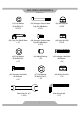
INCLUDED HARDWARE & TOOLS (19) Flat Washer Ø16xØ8.5x1.5 12 PCS (20) Hexagon Socket Head Cap Bolt M8x60mm 4 PCS (24) Nut Cap M8 4 PCS (26) Ring Pin Ø8x63.5mm 1 PC (28) Hexagon Socket Head Cap Bolt M8x20mm 4 PCS (42) Nylon Nut M8 5 PCS (43) Flat Washer Ø16xØ8.5x2.0 1 PC (44) Metal Bushing 1 PC (45) Hexagon Head Bolt M8x48mm 1 PC (46) Hexagon Head Bolt (47) Flat Washer M10x42mm 1 PC Ø18xØ10.5x2.
ASSEMBLY Step 1: Stand up the base of the machine by separating the frames as shown above. Pull the Rear/Front Frames (8, 9) as far apart as possible from each others and align the pin holes. Then insert the Ø8x63.5mm Ring Pin (26) from inner side into the holes on the Rear/Front Frames (8, 9) to lock the frames in place. Hardware: (26) Ring Pin Ø8x63.5mm 1 PC The product weighs more than 44 lbs and should be assembled and moved by two or more people.
ASSEMBLY Tool: Allen Wrench #6 1 Wrench (#13 & #17) Step 2: Attach the Handlebar (6) onto the Rear Frame (8) with two M8x60mm Hexagon Socket Head Cap Bolts (20), two M8 Nut Caps (24), and four Ø16xØ8.5x1.5 Flat Washers (19). Tighten bolts and nut caps with the Wrench and Allen Wrench provided. Repeat above same step to attach the other Handlebar (6) onto the Rear Frame (8). Hardware: (19) Flat Washer Ø16xØ8.5x1.
ASSEMBLY Tool: Allen Wrench #6 1 Wrench (#13 & #17) Step 3: Mount the Backrest Frame (2) to the Pivot Arms (11) by inserting the ends of the Pivot Arms (11) into the brackets, located at each side of the Backrest Frame (2), align to the bolt holes on the Pivot Arms (11) and brackets. Using four M8x20mm Hexagon Socket Head Cap Bolts (28), four Ø16xØ8.5x1.5 Flat Washers (19), and four M8 Nylon Nuts (42) to attach the Backrest Frame (2) onto the Pivot Arms (11).
ASSEMBLY Step 4: Pull up on the Adjustable Instep Frame Knob (40), slide the Adjustable Instep Frame (5) completely out of the Adjustable Boom (3) and then turn the Adjustable Instep Frame (5) with the adjustable holes facing up. Release the Adjustable Instep Frame Knob (40) and adjust the Adjustable Instep Frame (5) slightly until the Adjustable Instep Frame Knob (40) locks into place.
ASSEMBLY Tool: Slot 2 Wrenches (#13 & #17) Step 6: Slide the Rod (10) with both slots facing the Adjustable Instep Frame Knob (40) through the large round hole on the side of Adjustable Boom (3), and secure the Rod (10) on the Adjustable Boom (3) with one M8 Nylon Nut (42), one Ø16xØ8.5x2.0 Flat Washer (43), one Metal Bushing (44), and M8x48mm Hexagon Head Bolt (45).
ASSEMBLY Step 7: Slide one Front Heel Holder (13) onto one end of the Adjustable Instep Frame (5). Use the same procedure to attach the other Front Heel Holder (13) onto the other end of the Adjustable Instep Frame (5). Install two Adjustable Instep Frame Round End Caps (39) onto both ends of the Adjustable Instep Frame (5) and Front Heel Holders (13). Step 8: Pull out the Adjustable Boom Knob (41), and slide the Adjustable Boom (3) into the square bracket on the bottom of the Backrest Frame (2).
ASSEMBLY Step 9: Attach the Nylon Strap (23) to the strap lock on the Loop Strap (35) by inserting the end of the strap up through the bottom of the strap lock, loop the Nylon Strap (23) over the Pre-assembled Loop Strap (35) and down through the strap lock on the Loop Strap (35). Now, loop the strap back over itself, and insert back through the strap lock on the Loop Strap (35), and pull tight to secure. See diagram.
OPERATION AND ADJUSTMENTS SHORTEN LENGTHEN THE STRAP For added safety, a nylon strap has been included to restrict the degree of inversion. This strap can be adjusted to different lengths to allow for a greater or lesser degree of inversion. To lengthen the Nylon Strap (23) feed the top end of Nylon Strap (23) into the strap lock, and pull on the lower end of the strap. To shorten the length feed the bottom end of Nylon Strap (23) into the strap lock, and pull on the top end.
OPERATION AND ADJUSTMENTS THE HANDLEBARS For added convenience and safety, a set of Handlebars (6) has been added to the inversion table. These Handlebars (6) are located at the top of the Rear Frame (8). The Handlebars (6) are there to help you return to the upright position from any degree of inversion. If you wish to return to the upright position, and the backrest is moving too slowly, or not moving at all, simply grab the Handlebars (6) and pull on them until you return to the upright position.
OPERATION AND ADJUSTMENTS ADJUSTING THE FRONT AND RUBBER REAR HEEL HOLDERS 1. 2. 3. 4. Pull up on the Adjustable Instep Frame Knob (40), slide the Adjustable Instep Frame (5) completely out of the Adjustable Boom (3). Slide your ankles between the Front and Rear Rubber Heel Holders (13, 14) and stand on the Foot Bar (4) located at the bottom of the Adjustable Boom (3). Pull up on the Adjustable Instep Frame Knob (40), allow the Adjustable Instep Frame (5) to slide back into the Adjustable Boom (3).
OPERATION AND ADJUSTMENTS USING THE INVERSION TABLE 1. 2. 3. 4. 5. 6. Start by lying fully back on the backrest with your hands at your side, or resting on your thighs. Keeping your hands close to your body begin to raise your arms slowly allowing the table to rotate backward. Stop, or lower your arms to control the downward rotation of the table. Raise your arms until they are over your head. At this point, the inversion table will be as far back as it can go.
OPERATION AND ADJUSTMENTS SUGGESTIONS FOR USE 1. Begin slowly: invert only 15~20 degrees to begin with. Stay inverted only as long as you are comfortable. Return upright slowly. 2. Make gradual changes: increase the angle only if it is comfortable. Increase angle only a few degrees at a time. Increase the time of use 1~2 minutes up to ten over a period of weeks. Add stretching and light exercise only after you are comfortable with inversion. 3. Watch your body.
STORAGE For your storage convenience, the inversion table can be folded down to place against a wall, under a bed, or in a storage area. Pull out the Ring Pin (26) from the holes on the Rear and Front Frames (8, 9), then push the Rear and Front Frames (8, 9) together until they meet. Insert the Ring Pin (26) back into the hole on the Front Frame (9). Now the inversion table is ready to be stored, allowing you to unfold it quickly and easily whenever you want to use it.
WARM UP Quadriceps Stretch With one hand against a wall for balance, reach behind you and pull your right foot up. Bring your heel as close to your buttocks as possible. Hold for 15 counts and repeat with left foot up. Inner Thigh Stretch Sit with the soles of your feet together with your knees pointing outward. Pull your feet as close into your groin as possible. Gently push your knees towards the floor. Hold for 10 counts.
WARRANTY Paradigm Health & Wellness, Inc. warrants to the original purchaser that this product is free from defects in material and workmanship when used for the purpose intended, under the conditions that it has been installed and operated in according to Paradigm’s Owner’s Manual. Paradigm’s obligation under this warranty is limited to replacing free of charge, any parts which may prove to be defective under normal home use.
FAX FORM PARADIGM PARTS REQUEST FAX FORM Please fax this form to (1-626-810-2166) OR YOU CAN EMAIL CUSTOMER SERVICE REQUESTS TO service@paradigmhw.