Installation Manual MODEL: UD-42
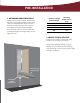
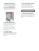
GET TO KNOW YOUR UNIT 2 1 5 4 (BOTTOM OF RACEWAY) 3 1. CROSS BRACES 4. ELECTRICAL OUTLET 2. ELECTRICAL RACEWAY 5. HOT IRON REST 3.
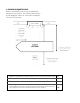
PRE-INSTALLATION 1. DETERMINE MOUNTING HEIGHT Using the charts provided, determine the mounting height above floor (the distance between the floor and the bottom of the cabinet). First choose your desired ironing board height from the left column, then locate the corresponding mounting height in the right column. Desired Ironing Board Height Mounting Height Above Floor 32” 31” 30” 29” 16” 15” 14” 13” 2. LOCATE STUDS & UTILITIES Using a stud finder, locate the wall studs to be used for mounting.
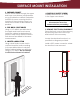
3. ENSURE ADEQUATE SPACE Refer to provided chart to ensure adequate clearance for ironing. The cabinet door opens at 180 degrees; allow 16” from side of cabinet for door to fully open. 1. Distance needed on either side of unit to fully swivel the board 167/8” 2. Distance from wall to tip of ironing board 501/4” 3. Distance from wall to board when in full swivel position 321/4” 4.
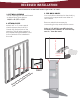
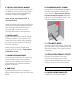
RECESSED INSTALLATION Note: Instructions assume wall studs are spaced 16” on center. 1. CUT WALL OPENING 3. PRE-DRILL HOLES 2. ATTACH CLEATS Remove electrical raceway by unscrewing the top and bottom screws. Your unit will be attached to the studs by screws in the upper and lower sides of the cabinet. Cut an opening into the wall based on dimensions given below. 14 3/8” x 59 7/8” x 3 7/8” Attach a 2” x 4” cross support cleat between the studs so it is level with the bottom of the opening.
. INSTALL UNIT IN WALL Ensure that power is disconnected at service entrance before proceeding. Begin installation by carefully lifting unit into the wall opening. Make sure the cabinet is plumb and level. If needed, add shims to help unit fit snug in place. 4. REMOVE ELECTRICAL KNOCKOUT Open the front cover of the raceway by removing the screw at the top and bottom of the raceway. Locate the electrical knockout, as specified on diagram provided. 7.
8. REMOVE BRACKET SCREW Locate side ironing board brackets that are secured to cabinet with three screws. Then remove the top screw from each bracket. This is where the bottom part of your cabinet will be secured to the studs. 11. REPLACE RACEWAY COVER Place the raceway cover into position, ensuring that no wires are pinched. Reinstall the top and bottom screw to secure in place. Reconnect power supply. 12.
SURFACE MOUNT INSTALLATION 1. PREPARE CABINET Screws will be drilled through the upper and lower cross braces (see illustration on pg.3) inside the cabinet. Determine location of screws, ensuring that the location of the mounting screw is as close to the center of the cabinet as possible. 2. PRE-DRILL PILOT HOLES Using a 1/4” drill bit, pre-drill holes in the upper and lower cross braces inside the cabinet as determined in previous step.
6. INSTALL ELECTRICAL WIRING Verify that there is ample supply wire available to run from the top of the ironing center to the approximate location of electrical pigtails. Note: A free wire length of 48” is recommended. 10. REMOVE BRACKET SCREW Locate side ironing board brackets that are secured to cabinet with three screws. Then remove the top screw from each bracket. Replace with a #14 x 3/4” Phillips screw. This will add stability long-term.