
Installation Sheet
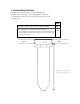
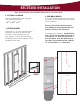

5. INSTALL ELECTRICAL WIRING
2
1/2”
2
1/4”
1
1/4
”
DIA. VENT
HOLE FOR
WIREWAY
DOOR
CABINET
EXTERIOR
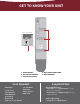
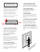
4. REMOVE ELECTRICAL KNOCKOUT
Open the front cover of the raceway
by removing the screw at the top
and bottom of the raceway.
Locate the electrical knockout, as
specied on diagram provided.
Install a 3/8” romex connector where
the knockout was removed.
Ensure that power is
disconnected at service
entrance before proceeding.
Verify that there is ample supply wire
available to run from the top of the
ironing center to the approximate
location of electrical pigtails.
Note: A free wire length of 48” is
recommended.
Begin to place the ironing center into
its location while feeding the supply
wire through electrical knockout, and
the 3/8” romex connector through the
back of the raceway.
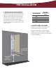
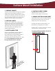
6. INSTALL UNIT INTO WALL
Begin installation by carefully lifting
unit into the wall opening.
Make sure the cabinet is plumb and
level. If needed, add shims to help
unit t space.
7. ATTACH CABINET TO STUDS
Using the pre-drilled holes in top of
cabinet, attach unit to studs with two
#10 x 1
1/2
” screws for top installation.
Finish installation by inserting the
#14 x 2
1/2
” screws in bottom
pre-drilled holes.
8. FINISH INSTALLATION
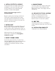
11. INSTALLATION COMPLETE!
Cabinet is now fully installed! If desired,
decorative trim or molding may be
added to cover any irregularities in the
wall.
Example shown with studs
to illustrate mounting.
9. CONNECT WIRES
Connect all power supply wires and
ground wires in accordance with
electrical codes. Trim supply wire as
necessary.
10. REPLACE ELECTRICAL RACEWAY
Place the raceway cover into
position, ensuring that no wires
are pinched. Reinstall the top and
bottom screw to secure in place.