Installation Manual MODEL E-46
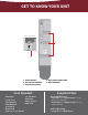
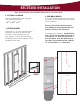
GET TO KNOW YOUR UNIT 2 (BOTTOM OF RACEWAY) 1 4 5 3 1. CROSS BRACES 2. ELECTRICAL RACEWAY 3. ELECTRICAL OUTLET Tools Needed: - Stud Finder - 12-14” Level - Tape Measure - Small Flathead Screwdriver - Electric Drill (with 1/4” & 1/8” drill bit) - 1/4” Nut Driver (optional) - Safety Glasses - Utility Knife 4. ELECTRICAL CORD COVER 5.
PRE-INSTALLATION 1. DETERMINE MOUNTING HEIGHT Using the charts provided, determine the mounting height above floor (the distance between the floor and the bottom of the cabinet). First choose your desired ironing board height from the left column, then locate the corresponding mounting height in the right column. Desired Ironing Board Height Mounting Height Above Floor 36” 35” 34” 33” 25” 24” 23” 22” 2. LOCATE STUDS & UTILITIES Using a stud finder, locate the wall studs to be used for mounting.
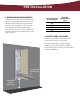
3. ENSURE ADEQUATE SPACE Refer to provided chart to ensure adequate clearance for ironing. The cabinet door opens at 180 degrees; allow 16” from side of cabinet for door to fully open. E46 Distance from wall to tip of ironing board Standing area clearance (not shown) The suggested distance from the side of the ironing where the user typically stands to ensure adequate space for ironing.
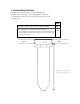
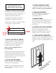
RECESSED INSTALLATION Note: Instructions based on installation between 16” on-center studs. 1. CUT WALL OPENING 3. PRE-DRILL HOLES 2. ATTACH CLEATS Remove electrical raceway before proceeding by removing the top and bottom screws on the raceway. Cut an opening into wall using the unit dimensions below: 143/8” x 597/8” x 37/8” Your unit will be attached to the studs by screws in the upper and lower sides of the cabinet.
Ensure that power is disconnected at service entrance before proceeding. 7. ATTACH CABINET TO STUDS Using the pre-drilled holes in top of cabinet, attach unit to studs with two #10 x 11/2” screws for top installation. 4. REMOVE ELECTRICAL KNOCKOUT 8. FINISH INSTALLATION Open the front cover of the raceway by removing the screw at the top and bottom of the raceway. Finish installation by inserting the #14 x 21/2” screws in bottom pre-drilled holes.
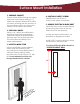
Surface Mount Installation 1. PREPARE CABINET Screws will be drilled through the upper and lower cross braces (see pg. 11) inside the cabinet. Determine location of screws, ensuring that the location of the mounting screw is as close to the center of the cabinet as possible. 2. PRE-DRILL HOLES Using a 1/4” drill bit, pre-drill holes in the upper and lower cross braces inside the cabinet as determined in previous step. Ensure that the holes in both braces are drilled to the same measurement. 3.
6. INSTALL ELECTRICAL WIRING 9. CONNECT WIRES Verify that there is ample supply wire available to run from the top of the ironing center to the approximate location of electrical pigtails. Connect all power supply wires and ground wires in accordance with electrical codes. Trim supply wire as necessary. Note: A free wire length of 48” is recommended. 10.