
2020 Installation Instructions


Ironing Board
Height
Mounting
Height
RECESSED MOUNT INSTALLATION
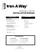
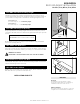
STEP ONE: Determine Mounting Height
46” Boards: 11”
Ex: Desired Height 35” - 11” = 24” Mounting Height
42” Boards: 7”
Ex: Desired Height 35” - 7” = 28” Mounting Height
UD-42: 16”
Ex: Desired Height 30”- 16” = 14” Mounting Height
FIGURE 1.1
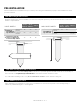
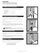
Beginning with the mounting height determined in Step One, cut an
opening in the wall based on dimensions given below for your specific
model:
46” Boards: 59 7/8” H x 14 3/8” W x 3 7/8” D
42” Boards: 51 1/4” H x 14 3/8” W x 3 7/8” D
UD-42: 59 7/8” H x 14 3/8” W x 3 7/8” D
Next, attach a 2” x 4” cross support cleat between studs, level with
bottom of opening (FIG 1.2)
STEP TWO: Cut Rough-In Opening
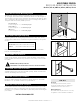
Using an 1/8” drill bit, pre-drill holes in the side walls of the cabinet
under the first cleat near the top (1 hole for each side), 2 1/2” from the
back wall.
STEP THREE: Pre-Drill Holes
FIGURE 1.2
Carefully lit and place unit into the wall opening. Plumb and level the
cabinet, shimming to fit if necessary.
STEP FOUR: Place Unit In The Wall
Using pre-drilled holes from Step Three, attach cabinet to studs with
two #10 x 1 1/2” provided screws for top installation.
STEP FIVE: Secure Top of Cabinet
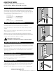
Locate swivel brackets near bottom of cabinet and remove top screws
only from both sides. Pre-drill pilot hole into bracket and replace with
two #14 x 2 1/2” provided screws (FIG 1.3). This will provide anchoring for
your swivel.
STEP SIX: Secure Bottom of Cabinet
FIGURE 1.3
INSTALLATION COMPLETE!
Drywall not shown.
Identify your desired ironing board height (typical ironing board is
33”-35” high). Then subtract the number below based on the length of
your model’s ironing board to determine mounting height (FIG 1.1). Take
into consideration the adjusted position of your ironing board, which is
4” higher than the normal, default position.
ADJUSTABLE SWIVEL
ADJUSTABLE SWIVEL IRONING CENTER | PG. 3
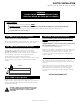
PRO TIPS:
If installing an electrical unit, remove
electrical raceway before pre-drilling top
installation holes for easier access.
Electrical
Decorative trim may be added to cover any
irregularities in the wall ater installation
Wall Irregularities
MODELS AE46, AE42, & UD42:
PLEASE REFER TO ELECTRICAL INSTRUCTION ON PG. 7 BEFORE PROCEEDING.
Models | AE46, ANE46, AE42, ANE42, UD42