
Installation Sheet


SURFACE MOUNT INSTALLATION
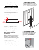
2. PRE-DRILL PILOT HOLES
Using a 1/4” drill bit, pre-drill holes in
the upper and lower cross braces
inside the cabinet as determined in
previous step. Ensure that the holes in
both braces are drilled to the same
measurement.
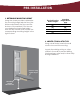
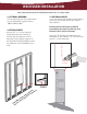
1. PREPARE CABINET
Screws will be drilled through the
upper and lower cross braces inside
the cabinet. Determine location of
screws, ensuring that the location of the
mounting screw is as close to the center
of the cabinet as possible.
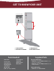
Example shown with
studs & unit to illustrate
mounting.
Partially insert a #14 x 4” screw
in the upper cross brace.
4. PARTIALLY INSERT SCREW
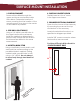
3. LOCATE & MARK STUD
Using a stud nder, locate stud in wall
and mark the wall according to the
pre-drilled holes in cabinet. Setting
cabinet aside, pre-drill holes in wall
using a 1/4” drill bit. Do not attempt
to mount only through hard board of
cabinet.
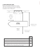
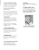
5. REMOVE ELECTRICAL KNOCKOUT
Open the front cover of the raceway
by removing the screw at the top
and bottom of the raceway.
Locate the electrical knockout, as
specied on diagram provided.
Install a 3/8” romex connector where
the knockout was removed.
Position of Electrical Knockout for
SURFACE MOUNT ONLY
24
1/2
”
2
13/16
”