
Installation Sheet
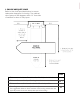
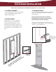


5. INSTALL ELECTRICAL WIRING
2
1/2”
2
1/4”
1
1/4
”
DIA. VENT
HOLE FOR
WIREWAY
DOOR
CABINET
EXTERIOR
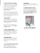
4. REMOVE ELECTRICAL KNOCKOUT
Open the front cover of the raceway
by removing the screw at the top
and bottom of the raceway.
Locate the electrical knockout, as
specied on diagram provided.
Install a 3/8” romex connector where
the knockout was removed.
Ensure that power is
disconnected at service
entrance before proceeding.
Verify that there is ample supply wire
available to run from the top of the
ironing center to the approximate
location of electrical pigtails.
Note: A free wire length of 48” is
recommended.
Begin to place the ironing center into
its location while feeding the supply
wire through electrical knockout, and
the 3/8” romex connector through the
back of the raceway.
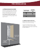
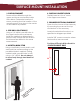
7. ATTACH CABINET TO STUDS
Using the pre-drilled holes in top of
cabinet, attach unit to studs with two
#10 x 1
1/2
” screws for top installation.
Locate side ironing board brackets
that are secured to cabinet with
three screws. Then remove the
top screw from each bracket. This
is where the bottom part of your
cabinet will be secured to the studs.
8. REMOVE BRACKET SCREW
Example shown with studs
to illustrate mounting.
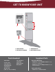
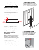
6. INSTALL UNIT IN WALL
Begin installation by carefully lifting unit
into the wall opening. Make sure the
cabinet is plumb and level. If needed,
add shims to help unit t snug in place.