200 Range Dialer Installation Manual Version 1.
The information contained is supplied without liability for any errors or omissions. No part may be reproduced or used except as authorised by contract or other written permission. The copyright and foregoing restriction on reproduction and use extend to all media in which the information may be embedded.
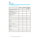
Contents 1. Introduction ...................................................................................................... 1 1.1. About this manual… .............................................................................. 1 1.2. Overview ................................................................................................ 1 1.3. System specifications ............................................................................ 2 2. Before you start… .................................
ii Iris Touch 200 Range Dialer Installation Manual
1. Introduction 1.1. About this manual… This manual is designed to help you, the Installer, with the installation process for the IRIS Touch alarm dialer. We recommend that you read through this manual, in its entirety, before you visit the customer’s site and begin the installation. 1.2.
1.3.
2. Before you start… 2.1. Package contents In this package you should have the following components: • Main dialer unit comprising: • • • PCB with 3 part plastic enclosure (back, front and slider). 4 x assembly screws. 2 x tamper switch springs. • • Power cable (black) for connection to DC supply. • • • • • Antenna for GSM/GPRS. (GSM / Ethernet & GPRS only). 2.2. Ethernet cable (cream) for connection to IP network. (Ethernet / Ethernet & GPRS only).
3. Alarm dialer interface IRIS dialers carry alarm signals from the alarm panel over IP completely transparently so when they arrive at the Monitoring Centre it is as though they had come over a traditional PSTN connection. IRIS dialers support SIA (Levels 1 to 3), Contact ID, Scancom (Fast Format) and Robofon protocols, one of which virtually all alarm panels will support. Apart from the following, no reconfiguration of the alarm panel is required for use with IRIS dialers: 1.
1. Decide where to run the cables Decide the best way to run the cables to the PCB. This can be either: • • Behind the unit (through the wall). Through the bottom of the back plate of the unit (via the ‘knock outs’). 2. Disassemble the unit Remove the two case fixing screws [1] and open the unit [2]. Remove the two PCB fixing screws [3] and remove the PCB. 3.
7. Fit the PCB to the back plate Fit the PCB to the back plate, aligning the corners of the plate with the edgings on the back plate and the two bottom screw fittings [13]. Screw in the 2 top screws only [14]. 8. Fit the SIM card (GSM / Ethernet & GPRS only) Fit the SIM card [15]. Power must not be applied to the PCB while the SIM card is being fitted or removed or it may be damaged. 9. Plug in the external cables • Plug the dialer cable into the alarm panel dialer.
5. Configuring the IRIS Touch Dialer The majority of configurations can be carried out via the touch screen interface display on the IRIS dialer. For more complex systems, for example where the data port is used, additional configuration is available via the USB connector using a laptop / PC and IRIS dialer configuration software (available via the Chiron website).
6. Post installation Once you have completed the installation you must: • Ensure the system is running correctly, the LED light on top of the unit is on steady and alarms are being signaled to the Monitoring Centre correctly. • After a short period of inactivity the display will switch off. To switch it back on, touch the display anywhere. • If a fault should develop, then the LED light on the top of the unit will start flashing and the display will show a system fault message.
7.1. Installation Each PIN input is designed to be connected in a loop via an open/close contact source from an alarm panel, or other device, to a reference ground PIN [19] available on the IRIS dialer, as shown below: Reference ground Pin inputs 1 4 Opening the contact (i.e. loop is open circuit) generates an alarm signal. Closing the contact generates the equivalent restore signal.
7.2. Default alarm messages The default SIA messages for each PIN are shown below: Pin ‘Set’ message ‘Restore’ message Meaning 1 NBA01 NBR01 Burglary alarm/restore 2 NFA02 NFR02 Fire alarm/restore 3 NQA03 NQR03 Emergency alarm/restore 4 NOP04 NCL04 Open/close 8. Relay outputs The IRIS dialer has two relay outputs [20] that can be used in a number of ways: • • • To indicate communications path failure. Activation by incoming SMS Message. Setting by the Monitoring Centre.
Appendix A – Settings menu Setting Purpose Network Interfaces Selects which network interfaces are going to be used (i.e. Ethernet and/or Ethernet/GPRS). Stops dialer reporting trouble on interfaces not being used. Account Number/Name The IRIS account number/name, as allocated by the Monitoring Centre. Monitoring Centre IP Address IP address of the receiver at the Monitoring Centre. Dialer IP Address IP address of the dialer, i.e. either automatic (DHCP) or fixed.
Appendix B – Installation photos [1] [2] [3] [6] [4] [5] 12 Iris Touch 200 Range Dialer Installation Manual
[14] [11] [8] [15] [12] [10] [9] [7] [13] [17] [19] [18] [20] [16] Iris Touch 200 Range Dialer Installation Manual 13
Appendix C – Specification Alarm Dialer Interface Two wire interface via RJ11 socket 40V feed at 12mA Ringing voltage 40V P-P to REN4 for incoming calls Off hook detection with dial-tone presented to alarm dialer DTMF tone recognition for dialing outgoing calls and alarm signaling Ethernet Interface 10Mbps and 100Mbps (10/100BaseT) with auto-negotiation UTP with standard RJ45 socket for CAT-5 cabling Dynamic IP addressing (DHCP) or fixed GSM/GPRS Interface Dual band GSM 900 MHz and DCS 1800 MHz MMCX socket
Conformance The IRIS range of alarm dialers comply with the following European Directives: • • • 1999/5/EC (Radio & Telecoms Terminal Equipment Directive). 72/23/EEC (Low Voltage Directive). 89/336/EEC (Electromagnetic Compatibility Directive as amended by 92/31/EEC).