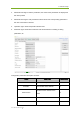
4. Software Setup 3. Parameter read region: read the parameters, the values of the parameters are displayed in this area by Read. 4. Parameter write region: write parameter. Entered value of the corresponding parameter in this area can be write to detector. 5. Operation region: functional operation buttons area. 6. Status bar region: status bar for detector state and information of reading or writing parameters, etc. Configuration parameters description as below: Name Product No. Serial No.
Mars1717V-VSI Digital Flat Panel Detector User MCU Arm Version Version number of the ARM App N Kernel Version Version number of ARM Kernel N Tirgger mode of the detector Y Trigger Mode Set Delay Time(ms) Exp Window Time(ms) Src IP Src MAC Exposure window for AED mode which use a fixed window Max exposure window for command trigger which use a dynamic window Y Y Detector IP Y Detector MAC Y DHCP, Client, not set as on with WLAN DHCP Enable LAN DHCP enabled at the same Y time.
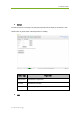
4. Software Setup Sensor The mainly function in this page is to probe the temperature and humidity of the detector. Click “Read” button to get the value of the temperature or humidity.
Mars1717V-VSI Digital Flat Panel Detector User User can config the wireless connect parameters on this tab. Images You can Query and upload Images from detector to Workstation. iRay Technology Co.
4. Software Setup 4.4.5. Calibrate Page Offset, Gain, Defect calibrate files can be generated and managed in this page.
Mars1717V-VSI Digital Flat Panel Detector User Click “Start Generate Templates” to enter generating templates page. SubTab Description Mode&Files Manage template files Create Offset Create Offset template Create Gain Create Gain template Create Defect Create Defect template Mode&Files page Description Import to Workdir Copy template file into current calibration directory. Download to FPD Select one item first. Then click this button to download selected template file(s) into detector.
4. Software Setup Upload Lag Upload Lag into SDK current directory Active Select one item in list. Click this button to activate selected template for hardware correction. UpdateHWPreOffset Force detector update Offset template(not needed for postoffset flow) ReadStatus Get the current state of template for hardware correction, enable/disable Generate Gain Template File If the relative position between tube and detector changed or KV value changed, it suggest to create gain template file. 1.
Mars1717V-VSI Digital Flat Panel Detector User 2. Click PREP button, then exposure after Acquire button enable. After receving the PREP request, the detector needs some time to be ready, the decounting bar will apear when the exposure window is opened. After exposure user can click Acquire button to acquire the XRay image. The gain template generation process needs 5 images total, the UI gives the recommended KV and target value, user can use different ones if needed.
4. Software Setup The current value box will show different colors, the definitons are as below: Yellow: The current value is higher or lower than the expected one, user decides if acceptable. For example, the expected value is 20000, and user needs 40000 as the gain piont, the yellow warning can be ignored, and the value can be accepted still. Green: The value is good. Red: The value is un-acceptable. 3.
Mars1717V-VSI Digital Flat Panel Detector User 4. When the generating process is finished, the UI will give the message of successful. Generate Defect Template File The process of generate defect map is quite similar with the one of gain map. 1. On the “Create Defect” page, user can start the generating process by “Start” button. And the process can be quit by “Cancel”. iRay Technology Co.
4. Software Setup 2. There are 8 images that need to be acquired, the UI gives the recommend KV and expected image value, user should refer with them. 3. If the option “Download to FPD after generation” is checked, the download UI will appear after finishing generating the defect map which will takes a little time. The field of “Index in FPD” means that the detector can store several correction maps and choose one set to active as user wants.
Mars1717V-VSI Digital Flat Panel Detector User 4. After choosing the stored index of FPD, the download process can be started by the “Download” button, user should wait the process until it is finished. 5. The correction map also can be managed at anytime on the page of “Mode&Files”. Choose the item of “Default” in the Subset settings part and click “Download to FPD” to finish downloading the maps into the detector. iRay Technology Co.
4. Software Setup Upload the correction files 1. The correction maps can be uploaded to the workstation too. Choose the gain or defect in the “Fpd template files”and the “Default” directory in the “Subset settings”, then click the “Upload to workdir”. 2. When the upload process is finished, the UI will give the message. The correction maps should be enabled before using hardware correction, read status first, then choose the gain or defect, enable the map by clicking “Active” button.
Mars1717V-VSI Digital Flat Panel Detector User 4.4.6. Local Page In this page user can open the image files saved in local, the file formate can be dcm, raw, tiff, dft. When the software is disconnected to detector, the file still can be opened. Click “Load File”, there will be an open file wizard. Select file and click open or double click the file. The tiff file will be opened directly. For the raw file or dft file there will be a dialog to select image size. Select correct size to open image files.
4. Software Setup This page provides ROI tool, which can see the AVG, SNR, and other properties of the choosen image area by right mouse button. This page provides WW/WL tool as Acquire page . Click this button to auto adjust WW/WL based on selected area by right button of mouse.
Mars1717V-VSI Digital Flat Panel Detector User Width Image width Height Image height Rotate the image clockwise, 90 degrees every time. Rotate the image anticlockwise, 90 degrees every time. Mirror Open or close mirror ROI ROI tool,to view the image of the AVG, SV, SNR and other parameters. Press "ctrl" key, can create several ROI area. WW/WL Auto adjust WW/WL based on selected area by right button of mouse. 4.5.
Wireless Digital Wireless Digital Flat Panel Detector Mars1417X 5. Operation Instructions for Image Acquisition 5.1. 5.2. 5.3. 5.4. 5.5. 54 User Manual of Mars1417X Steps for acquiring image ........................................................................ 66 Software Mode ........................................................................................ 66 AED Mode ............................................................................................... 68 After use ..................
5. Operation Instructions for Image Acquisition Mars1417X provides SDK for users to integrate detector into their DR system. Additionally, it also provides an application for demonstration, i.e. IDetector. User can use IDetector to control detector without DR system. 5.1. Steps for acquiring image Make sure the hardware is connected correctly and then power on.
5. Operation Instructions for Image Acquisition HVG X-Tube Work Station FPD 5.2.2. Work Flow(PrepAcq) Select HWPostOffset、HWGain、HWDefect. If user need the raw image, please de-select all these correction options. Also, the software correction is supported. Cmd_PrepAcq Ack_Prohibit Ack_Enable IDLE Prepare RAW Preview XWIN1 (fixed) RAW X‐Ray image (If HW‐offset is disabled) X‐Ray imaging XWIN1 (fixed) RAW offset(Or corrected) image Offset imaging 1. Send Cmd“PrepAcq” on UI “Acquire” page.
Wireless Digital Wireless Digital Flat Panel Detector Mars1417X 6. The preview image will be always sent, which is 4x4 averaging, the raw X-Ray image will be sent if the HW correction is disabled with the raw offset image follows, otherwise, the XRay image will not be sent and only the corrected image will be transferred. 5.2.3.
5. Operation Instructions for Image Acquisition 5.3.1. Inner Prep Low power 1. Ack X‐Ray IDLE RAW X‐Ray image RAW Preview (If HW‐offset is disabled) Info XWIN1 (fixed) X‐Ray imaging XWIN1 (fixed) RAW Offset(Or corrected) image Offset imaging The detector is in low power state, user needs to send Cmd “Prep” to make the detector exit to idle state which indicated by the acknowledge to Cmd “Prep”. 2. When the detector is in idle state, user can start the X-Ray any time. 3.
Wireless Digital Wireless Digital Flat Panel Detector Mars1417X 5.3.3. X‐Ray RAW X‐Ray image RAW Preview (If HW‐offset is disabled) Info IDLE XWIN1 (fixed) X‐Ray imaging XWIN1 (fixed) RAW Offset(Or corrected) image Offset imaging 1. For Freesync mode, there is no low power state. 2. When the detector is Idle, user can start the exposure flow any time. 3.
5. Operation Instructions for Image Acquisition “Upgrade Firmware”. The firmware upgrade package may contain firmware of several units: ARM, FPGA, MCU. Mars1417X_IMAGE_44_ALL_20XX_XX_XX.ifrm Word “ALL” indicates the file contains the firmware upgrade file for all units. Mars1417X_IMAGE_44_ARM_20XX_XX_XX.ifrm Word “ARM” indicates the file is only for ARM. Mars1417X_IMAGE_44_FPGA_20XX_XX_XX.ifrm Word “FPGA” indicates the file is only for FPGA. Mars1417X_IMAGE_44_MCU_20XX_XX_XX.
Wireless Digital Wireless Digital Flat Panel Detector Mars1417X 60 Manual of Mars1417X User
6. Regulatory Information 6. Regulatory Information 6.1. 6.2. 6.3. 6.4. 6.5. User Manual of Mars1417X Medical Equipment Safety Standards ..................................................... 74 Guidance and Manufacture’s Declaration for EMC ................................. 75 Radio Frequency Compliance Information .............................................. 78 Battery Safety Standards ........................................................................ 81 Product Label ...........................
Wireless Digital Wireless Digital Flat Panel Detector Mars1417X 6.1.
6. Regulatory Information 6.2. Guidance and Manufacture’s Declaration for EMC 6.2.1. EMI Compliance Table Emissions Phenomenon Compliance Electromagnetic environment RF emissions CISPR 11 Professional healthcare facility environment Group 1, Class B Harmonic IEC 61000-3-2 distortion Voltage fluctuations and Professional healthcare facility Class A IEC 61000-3-3 environment Professional healthcare facility Compliance environment flicker 6.2.2.
Wireless Digital Wireless Digital Flat Panel Detector Mars1417X 450 430-470 FM, ±5kHz deviation, 1kHz sine, 28V/m 710 704-787 Pulse modulation 217Hz, 9V/m 800-960 Pulse modulation 18Hz, 28V/m 1700-1990 Pulse modulation 217Hz, 28V/m 745 780 810 870 930 1720 1845 1970 62 Manual of Mars1417X User
7. Trouble Shooting 2450 2400-2570 Pulse modulation 217Hz, 28V/m 5240 5100-5800 Pulse modulation 217Hz, 9V/m 5500 5785 Input a.c. power port Phenomenon Electrical fast transients/burst Surges Line-to-line Surges Line-to-ground Basic EMC standard Immunity test levels Professional healthcare facility environment ±2 kV IEC 61000-4-4 100kHz repetition frequency IEC 61000-4-5 ±0.5 kV, ±1 kV IEC 61000-4-5 ±0.5 kV, ±1 kV, ±2 kV 3V, 0.
Wireless Digital Wireless Digital Flat Panel Detector Mars1417X Electromagnetic Compatibility (EMC) Mars1417X requires special precautions regarding EMC and needs to be installed only by iRay or authorized personnel and put into service according to EMC information provided in the user manual. Mars1417X in use may be susceptible to electromagnetic interference from portable and mobile RF communications such as mobile (cellular) telephones.
6. Regulatory Information Contains module’s FCC ID:2ACHK-01070189 The panel has been tested to comply with limits for a Class B digital device, pursuant to part 15 of FCC Rules. These limits are designed to provide reasonable protection against harmful interference in a residential installation.
Wireless Digital Wireless Digital Flat Panel Detector Mars1417X Operation is subject to the following two conditions. The panel may not cause harmful interference. The panel must accept any interference received, including interference that may cause undesired operation. The panel generates, uses, and radiates radio frequency energy and, if not installed and used in accordance with the instruction, may cause harmful interference to radio communications.
6. Regulatory Information the maximum value. This is because the device is designed to operate at multiple power levels so as to use only the power required to reach the network. In general, the closer you are to a wireless Base station antenna, the lower the power output. The exposure standard for wireless devices employing a unit of measurement is known as the Specific Absorption Rate, or SAR. The SAR limit recommended by the ICNIRP used by the general public is 2.
Wireless Digital Wireless Digital Flat Panel Detector Mars1417X 70 Mars1417X User Manual of
6.
Wireless Digital Wireless Digital Flat Panel Detector Mars1417X Battery Label 70 Mars1417X User Manual of
6. Regulatory Information 7. Trouble Shooting Please refer to service manual. If the problem persists, turn off the panel and contact iRay service department (service@iraygroup.com). We would provide the best service.
Wireless Digital Wireless Digital Flat Panel Detector Mars1417X 8. Service Information 8.1. 8.2. 8.3. 8.4. 8.5. 86 anual of Mars1417X Service Office Information ....................................................................... 87 Product Lifetime....................................................................................... 87 Regular Inspection and Maintenance ...................................................... 87 Repair ..................................................................
8. Service Information 8.1. Service Office Information 8.2. Product Lifetime The estimated product lifetime is up to 5 years under appropriate regular inspection and maintenance. 8.3. Regular Inspection and Maintenance In order to ensure the safety of patients and operator, to maintain the performance and reliability of the panel, be sure to perform regular inspection at least once a year. If necessary, clean up the panel, make adjustments or replace consumables such as fuses etc.
Wireless Digital Wireless Digital Flat Panel Detector Mars1417X 8.5. Replacement Parts Support Main parts (parts required to maintain the function of the product) of this product will be stocked for 5 years after discontinuance of production for repairing.
APPENDIX APPENDIX A INFORMATION OF MANUFACTURES ....................................................... 76 APPENDIX B INFORMATION OF EUROPE REPRESENTATIVE.....................................
Wireless Digital Wireless Digital Flat Panel Detector Mars1417X COMPANY: iRay Technology Taicang Ltd. ADDRESS: No.33 Xinggang Road, Taicang Port Economic and Technological Development Zone, Jiangsu, China ZIP CODE: 215434 TELEPHONE: +86 0512-53690872 FAX: +86 0512-53690872 HOMEPAGE: WWW.IRAYGROUP.
APPENDIX Appendix B COMPANY: iRay Europe GmbH ADDRESS: IN DEN DORFWIESEN 14, 71720 OBERSTENFELD Information of Europe Representat ive User Manual of Mars1417X 91 GERMANY ZIP CODE: / TELEPHONE: +49-7062-977 88 00 FAX: +49-7062-976 0571 HOMEPAGE: WWW.IRAYEUROPE.