
User's Manual
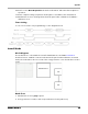
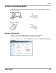
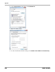
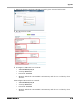
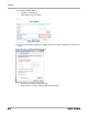
Table Of Contents
- 1 Notices and Conventions
- Contents
- 1 Notices and Conventions
- 1 Safety and Regulatory Information
- 2 Overview
- 3 Installation
- 4 Operation
- A Appendix
- Software and Settings A-1
- Operating Modes A-8
- Software Installation A-12
- Set the Connection Mode A-13
- Shortcuts A-24
- Establish a Connection with the Detector A-25
- Configure the Detector A-26
- Correction and Calibration Template Generation A-29
- Image Check and Upload A-35
- Defect Template Check and Modification A-37
- Correction and Calibration Management A-40
- Update the Firmware A-44
- Publication History
- 1 Safety and Regulatory Information
- 2 Overview
- 3 Installation
- 4 Operation
- A Appendix
- Software and Settings
- Operating Modes
- Software Installation
- Set the Connection Mode
- Shortcuts
- Establish a Connection with the Detector
- Configure the Detector
- Correction and Calibration Template Generation
- Image Check and Upload
- Defect Template Check and Modification
- Correction and Calibration Management
- Update the Firmware
- Publication History

Appendix
AJ4309 | 2019-08-13 A–9
10. Panel receives Data Acquisition from the workstation and starts data acquisition
operation.
11. Panel completes image acquisition and begins to send data to the workstation.
12. Workstation receives all image data from the panel after calibration if hardware
calibration is on.
Time Setting
To set a clear scenario for programming, see the diagram below.
Inner2 Mode
Block Diagram
The workstation is a host PC device installed with iDetector and SDK. Installation
describes how to establish connections between the panel and workstation. In inner2
mode, the workstation does not control the x-ray generator. Users decide when to take
x-rays.
Work Flow
1. Workstation receives prep request.
2. X-ray generator is ready to take x-rays and starts releasing the x-ray.