
Data Sheet

IRONBOY USER MANUAL Ver.1.03_Eng
27
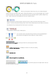
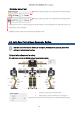
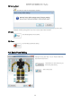
As shown in left picture, make angle 140˚ between ID 2 and 4. And the axis of
ID 2 and 4 should be aligned in straight line (see Yellow line in the picture)
On ID 3 servo basis, make 70˚ between "ID2 and 3" and "ID4 and 3" as well.
As shown in right picture, make angle 140˚ between ID 8 and 10. And the
axis of ID 8 and 10 should be aligned in straight line (see Yellow line in the
picture)
On ID 9 servo basis, make 70˚ between "ID8 and 9" and "ID10 and 9" as
well.
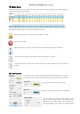
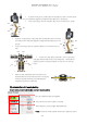
In front view, align pelvis motors (ID 1 and 7) as picture so
that upper & lower body can be in the straight line. And make arm
position as shown in the picture (set ID 17 and 12 in 90˚ from the
body. )
Palms of robot should look forth front side. Set 90˚
between elbow and main body as shown in the picture.
From the shoulder and hands, it should alsgned in
straight line as shown as yellow line.
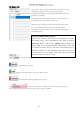
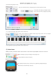
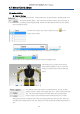
(2) Actuator(Servo) Property Setting
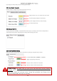
Servo ID setting, motor enable/disable, movement test are available.
Servo ID of selected motor (Changeable).
Servo will function when "Enable" is checked.
Motor direction can be changed. (Normal/Reverse)
※ Note : If there are already created motion library, please be careful
ID1
ID7
ID17 ID12
ID8
ID9
ID10
ID2
ID3
ID4