Arduino Compatible Open Source Humanoid ------ IRONBOY(IRH IRONBOY(IRH-100) User ser Manual
IRONBOY USER MANUAL Ver.1.03_Eng INDEX 01Before Use 03 Introduction Specification 03 05 For Safety Battery & Charger 06 08 02 Composition Pack Composition Names & Description Joint Structure & Names 03 Main Controller Main Feature Names & Description 04 Total Manager Robotics for everybody. 09 09 09 12 13 13 15 16 Operating Condition 16 Installation 17 Comm.
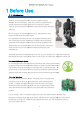
IRONBOY USER MANUAL Ver.1.03_Eng 1 Before Use. 1.1. Introduction Thank you for purchasing world's First Arduino compatible Humanoid IRONBOY, IRH-100. The IRduino, - Open source Arduino compatible board is basically included in the package to expand your humanoid functionality drastically. For safe & joyful use of IRON IRONBOY, please read this manual thoroughly before use. IRH-100 consists of 16 durable digital servo motors, dedicated main control board and metal frames with other hardware.
IRONBOY USER MANUAL Ver.1.03_Eng IRduino Board The IRduino is a microcontroller board based on the ATmega32u4 and it simply can be docked onto IRH-100's main board. It has 20 digital input/output pins (7 can be used as PWM outputs and 12 as analog inputs), a micro USB connection, a power jack, an ICSP header, and a reset button. To manage port expandability efficiently, user may select between Hardware serial and Software serial communication.
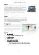
IRONBOY USER MANUAL Ver.1.03_Eng 1.2. Specification [IRH-100 IRONBOY] Control System Pulse Width Modulation Control, 1500usec Neutral Degree of Freedom 16 DOF (Max. expandable up to 24 DOF) Operating Voltage 5.5V ~ 7.0VDC (Ni-MH 5Cell Battery) Robot Control Mobile App Control via Bluetooth 4.
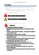
IRONBOY USER MANUAL Ver.1.03_Eng 1.3. For Safety Please note that damage or malfunction of the product caused by user's mistake or abuse may void warranty. Therefore, please read carefully this manual before use to prevent unexpected damage of the product and injury of users and follow instructions stipulated on this manual. Please read carefully below instructions for safety.
IRONBOY USER MANUAL Ver.1.03_Eng Pay attention to your fingers & head during robot operation. Fingers can be jammed between the joints during operation. Also keep proper distance your head from the robot to prevent unexpected injury. Make sure to put connector correctly. Otherwise it may damage circuitry or battery and may cause fire. Caution Secure enough space before robot operation. Robot operation in narrow space may cause damage of product due to the fall from the desk.
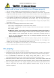
IRONBOY USER MANUAL Ver.1.03_Eng Caution - 1.4. Battery and Charger Things need to know to use Battery and Charger properly. 1. After full charging, IRONBOY can be operated between 10~30min according to motion level. 2. Basically, it is highly recommended to charge the battery full before use, then remove charger when charger shows green LED. Operate robot until robot shows low battery alarm in the red LED on the chest.
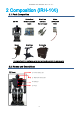
IRONBOY USER MANUAL Ver.1.03_Eng 2 Composition (IRH (IRH-100) 100) 2.1. Pack Composition IRH-100 Charger IRduino Board Micro B type Battery (Arduino compatible USB Cable (1500mA, 6V board) (For main board) NiMh) Robot Stand Carrying Bag * Inner paper box in the carrying bag can be used continuously to protect the robot properly. 2.2.
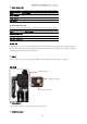
IRONBOY USER MANUAL Ver.1.03_Eng ① Power Status LED Round type RED LED on the chest shows power status as well as battery status. Status LED Indication Power S/W OFF OFF Power S/W ON ON (RED) Low Battery Flickering under less than 20% of battery capacity. ② Bluetooth Status LED This LED on the head shows Bluetooth module's power and connection status. Status LED Indication Bluetooth Power OFF OFF Bluetooth Power ON ON (WHITE) Bluetooth Connected ON (BLUE) RGB LED Editable RGB LED.
IRONBOY USER MANUAL Ver.1.03_Eng Connect the genuine battery (1500mA, 6V NiMH) with this connector to supply power. Charging Connector Connect the genuine charger to charge the battery. Full charging will take about 2 hours.
IRONBOY USER MANUAL Ver.1.03_Eng 2.3. Joint Structure and Names IRH-100 consists of joint structure and names as below. On the main board, each servo channel needs to be correspondent to each different servo. So, each servo must be connected to correct position of servo channels on the main board.
IRONBOY USER MANUAL Ver.1.03_Eng (3) Servo Number Total 24 different servos can be operated independently on the main board. As IRH-100 is 16 DOF humanoid, 16 servo channels have been assigned on the main board at the factory. Spare & empty channels can be activated in case of adding more DOF by users.
IRONBOY USER MANUAL Ver.1.03_Eng motion data saved in the controller can be uploaded to Total manager software (management program) for further task. Motion# Definition Description 0 ~ 99 MOTION_USER_00 ~ _99 User's motion 0 ~ 99 (To be saved in the external memory) MOTION_LIBRARY_00 ~ Library motion 0 ~ 99 (To be saved in 99 the internal memory) 200 MOTION_TORQUE_OFF All servos' torque will be removed. 201 MOTION_USER_TEST Temporary motion test while user 100 ~ 199 creates motions.
IRONBOY USER MANUAL Ver.1.03_Eng 3.2. Names and Description 9 3 6 5 1 4 1 2 7 8 12 10 10 11 (1) Servo Control Ports (24ch) Control ports for 24 servos. (Pulse width modulation) (2) Motion Data Memory 100 library motions, plus another 100 user's motion can be saved in the memory. ※ Among 100 library motions, first 20(#1~20) motions are finely tuned at factory. For the rest of 80motions library, user may do fine-tuning according to each robot's mechanical condition.
IRONBOY USER MANUAL Ver.1.03_Eng (8) IRduino Docking Connector IRduino board can be installed and works with the main board using this docking connector. (9) Connector for Chest PC Board Chest PC board includes Power indicator LED, RGB LED and Piezo. (10) Battery Connector Connector for Battery. (11) Charging Connector Connector for Charger. Battery needs to be installed in the robot before charging. Charging can be done in both cases - when robot power is OFF and robot power is ON.
IRONBOY USER MANUAL Ver.1.03_Eng [Required PC Specification for Total Manager ] ▶ OS : Windows XP Service Pack 2 / Vista/ 7 (32/64bit)/8 (32/64bit) or Higher ▶ 800MHz(or higher) 32bit(x86) or 64bit (x64) processor ▶ 512MB(or higher) system memory ▶ 500MB (or higher) hard disk space 4.2. Installation Follow instructions below to install Total Manager software. (1) Download Download "IRONBOY Total Manager" file from www.irrobot.com → "Digital Archive" menu.
IRONBOY USER MANUAL Ver.1.03_Eng 4.3. Communication Setting Connect IRH-100 with PC using USB wire and activate Total manager software. Then you will see intro screen as above. After then, power on the robot and follow instructions below. (1) Device driver will be installed automatically via internet when your IRH-100 is connected with your PC for the first time. (2) Check assigned COM port on "Device manager" (Below picture shows COM3 has been assigned, but it can be changed in your PC.
IRONBOY USER MANUAL Ver.1.03_Eng (3) Now, activate Total manager software and click "Retry" button on the intro screen. (4) COM port will be recognized automatically in your PC and you will see below screen. (5) If COM port is assigned incorrectly, click COM port menu(marked in red) below to see connected COM port list. Select connected COM port. (Example shows COM 3 is assigned.) If necessary, use COM port connect/disconnect icons shown above. (marked in blue.) 4.4.
IRONBOY USER MANUAL Ver.1.03_Eng Create new motion data. Previous motion data in the screen will be erased, so if necessary, save previous motion data before opening new one. Open : Open saved motion data Select & load saved motion data into current task window. Save : Save motion data Save current motion data with previous name. Save As : Save motion data as a different, new name. ② Tools Robot Basic Pose Open Robot basic pose window.
IRONBOY USER MANUAL Ver.1.03_Eng Open "User robot control(Virtual controller)" window IR Remote Setting : Combine Infrared remote controller codes with certain motions. ② COM Port Connection Automatic Search & connect available COM port Search & assign COM port. Connect COM port Disconnect COM port (3) Robot Joint Control (Step Pose) In this window, you can control servo motor and see the status of each servo's position.
IRONBOY USER MANUAL Ver.1.03_Eng When you click position value of each servo, you will see blue-green colored circle turns into Yellow color as above. Along with yellow line, you can drag small Red circle as a jog to change concerned servo's position value. Pay attention robot may lose balance due to sudden change of jog circle. Value will reset to 0 immediately when you click "CENTER" button. When this function is activated, position value of each servo will be synchronized with physical servo position.
IRONBOY USER MANUAL Ver.1.03_Eng (4) Motion List Space for 100 motions at User's motion area, and space for another 100 motions at factory Library motion area are provided. Multiple motions selection, motion upload/download functions are available in this window. 100 Factory Library motions will be shown in "Library" tap and you can make/save your own motions in "User" tab. Please note first 20 motions among 100 are finely tuned at factory.
IRONBOY USER MANUAL Ver.1.03_Eng (5) Motion Data Motion data shows each "Step" data for a motion and you can edit each step data. Also, Motion property setting and motion test are available. Each Step data shows Repeat setting status, Operating time(move time), Delay time(stop time), Robot inclination(Pitch & Roll) value, and positional value of each servo. Add new Step. Maximum 24 steps can be made for 1 motion. Remove selected Step. Adjust Step sequence.
IRONBOY USER MANUAL Ver.1.03_Eng pose and read its position value. Pitch and roll value setting. Angle setting to maintain balance of robot. Chest LED color setting for desired motion step. LED color will be changed according to selected number. ※ For color list for each LED number, refer to the annex. Piezo sound setting for desired motion step. Piezo sound will be changed according to selected number. ※ For scale list for each Piezo number, refer to the annex.
IRONBOY USER MANUAL Ver.1.03_Eng (8) Motion Adjust Tool All steps' operating & stop time of selected motion will get faster. All steps' operating & stop time of selected motion will get slower. Particular servo motor 's values in all steps of selected motion can be changed at once. (Offset & scale trim of selected servo can be adjusted) Left/Right symmetry value Swap for All steps of selected motion 4.5. Joint Zero Point & Basic Parameter Setting Click this icon on the tool bar.
IRONBOY USER MANUAL Ver.1.03_Eng As shown in left picture, make angle 140˚ between ID 2 and 4. And the axis of ID 2 and 4 should be aligned in straight line (see Yellow line in the picture) On ID 3 servo basis, make 70˚ between "ID2 and 3" and "ID4 and 3" as well. ID2 ID3 ID4 As shown in right picture, make angle 140˚ between ID 8 and 10.
IRONBOY USER MANUAL Ver.1.03_Eng to change servo motor direction as it will change all motions. (3) Robot Basic Property Robot ID, Battery voltage range, motion speed rate can be set. Assign robot ID. This is an unique # for each robot. Set full charging voltage of robot battery. Set low voltage alarm level of robot battery. Set motion speed rate. (4) Balance Control To be activated when "ENABLE" is checked.
IRONBOY USER MANUAL Ver.1.03_Eng (6) Factory Reset Click this icon and you will see below window. Click "Yes" Factory reset will proceed. It will take some time for factory reset, so please wait until it completes without cutting power. Click "No", factory reset will be canceled. (7) Save Save all setting data into the robot. (8) Close Exit from Basic parameter setting. 4.6. Basic Pose Setting Setting for basic pose value. You can freely modify basic pose value for each servo.
IRONBOY USER MANUAL Ver.1.03_Eng 4.7. Motion Edit & Library (1) Motion Editing ① Motion Creation Select desired motion tab. Please make sure if concerned motion is properly saved in the robot before motion editing.. "User" motion list should be made by users at their end, so you will see just blank page initially. The IRH-100 will be delivered with "Library" motions which saved at the factory. To make a new motion, click motion number, then click icon in "motion data" window.
IRONBOY USER MANUAL Ver.1.03_Eng Set "Move Time" value to control moving speed of concerned Step motion. Set "Stop Time" value to control delay time to next step motion. You can set LEDs in chest and Piezo of current step. Check desired function(LED and Piezo) and you will see different colors and hear different sound for each number. Create next step by clicking icon. You can repeat the same as 1st step to make a 2nd step. To make "Repeat section" for certain steps, click "Motion property" button.
IRONBOY USER MANUAL Ver.1.03_Eng When Motion or Motions are completed, select concerned motions or click "SelectALL" button. Then, click "Download" button to download selected motion library into robot.. After download, please make sure to save created library. Click "File" in the menu and select "Save" or "Save As". File format is "Robot motion data file" as shown in the picture, and file name can be made as you wish.
IRONBOY USER MANUAL Ver.1.03_Eng ③ Motion Test Motion will be shown as a graph with pitch and roll value. X axis show operating time and Y axis is pitch and roll graph based on 0 point. Stop button to complete Test ④ Download (Save motion to Robot) You will see progress bar and selected motion will be saved in the robot. ⑤ Motion Upload This button enables to upload motion to your PC from the robot. ⑥ Save Motion as file Selected motion files will be save as file in your PC.
IRONBOY USER MANUAL Ver.1.03_Eng Swap values in bilateral symmetry (between Left/Right servos) Tuning for servo positional value of particular joint See [Annex] Motion data Joint trim Increase for certain amount of Move time & Stop time Decrease for certain amount of Move time & Stop time (2) Motion Library Fine tuning for Motion number 100~123 will be done at factory.
IRONBOY USER MANUAL Ver.1.03_Eng 4.8. User Robot Control (Virtual Controller) (1) (2) (4) (5) (3) (1) Robot Motion List Saved motion list in the robot will be shown in this window. Motion number, name, next motion number are shown.
IRONBOY USER MANUAL Ver.1.03_Eng (2) Robot Control (Virtual Controller) F2 Button F1 Button Direction Button Figure Button Joystick L Joystick R Motion Status to be shown in this window. Direction buttons. (Up, Down, Left and Right). Match walking motions with these buttons. 4 different Figure buttons. Match desired motions with these buttons. 8 directional joystick(Up, down, left, right, 4 x diagonal directions) / 2 Joysticks on Left/Right side. Additional function buttons.
IRONBOY USER MANUAL Ver.1.03_Eng Current robot balance is shown in pitch(Front/Rear) & roll(Left/Right) standpoint. Elapsed time of controller. Press "stop" and "reset" button as you wish. Current battery capacity. Stability of pose in pitch and roll direction. (4) Robot Control Motion Binding You can assign desired motions to each joystick button. Assignment for buttons and Joysticks are separated.
IRONBOY USER MANUAL Ver.1.03_Eng Desired motions can be assigned to 10 different buttons below. In Joystick L tap, desired motions can be assigned to 8 different directions as below. In Joystick R tap, desired motions can be assigned to 8 different directions as below.
IRONBOY USER MANUAL Ver.1.03_Eng (5) Robot Real-Time Setting Motion speed rate can be set and other real time settings are available. Set motion speed rate. Lower rate makes motion faster and higher rate makes motion slower. This setting will be reflected to all motions and it does not mean that it changes original motion data. When this button is activated(ON), robot will stand up automatically when robot falls down. This function will be OFF when robot power is turned ON again. 4.9.
IRONBOY USER MANUAL Ver.1.03_Eng [Button Name] Put each Button name. [CODE] Unique code corresponding concerned remote button.(No need to put manually. See "Get code" below) [Motion ID] Put motion number to bind certain motion with certain remote button.. [Motion Name] Motion name will be shown automatically when Motion ID is assigned. Select concerned "CODE" area, then press concerned remote button, corresponding unique remote code will be shown automatically.
IRONBOY USER MANUAL Ver.1.03_Eng 5 Robot Control APP 5.1. Installation (1) Required Specification of Smart Phone Android OS 5.1 Lollipop or higher Bluetooth 4.0 BLE or higher (2) Installation File Download Download IRONBOY Controller APK from www. irrobot.com → Digital Archives (3) Installation Activate installation file (APK file). If you encounter block while installation, go to "Security" menu on your smart phone and enable "Unknown sources".
IRONBOY USER MANUAL Ver.1.03_Eng 5.2. Setting (1) Button Setting Click App Icon. In case Bluetooth is inactivated on your smart phone, you will see Bluetooth approval request as below. If Bluetooth is already activated, you will see main screen below. Click "Yes" [Bluetooth Approval Request] Press ① [Main Screen] key on Main screen, then you will see below setting page. Section 1 : Motion 0~199 can be assigned to 9 different figure keys freely.
IRONBOY USER MANUAL Ver.1.03_Eng ⑤ Section 5 : This is reset button. All setting values will be removed by this button. You will see the message for reset setting as right picture for confirmation. If you select "Yes", current value will be removed and reset to the initial status. Click "Save" button after the setting. Then, it will revert to the main screen. If robot ID in the above setting is out of 1~253, you will see message as left picture and the it will not be saved.
IRONBOY USER MANUAL Ver.1.03_Eng 5.3. Bluetooth Connection Turn on the robot power. Press button in main screen of the App, then you will see available Bluetooth list in “Scan Devices” window. (The name of bluetooth for IRH-100 is "IRONBOY".) Select your IRH-100's Bluetooth number. Then, screen will go to main control screen. Motion assigned keys will be shown with Green circle while grey circle keys show motion unassigned. 5.4.
IRONBOY USER MANUAL Ver.1.03_Eng (2) Control Screen Function ① Function Setting Button Function setting in the App will be removed when the robot power is off & on again while function setting in the total manager software will be kept constantly before user changes setting. Robot Control Rate : This is the command transfers speed (per sec) from App to the robot between the range 40~100ms.
IRONBOY USER MANUAL Ver.1.03_Eng ⑤ Left Control Panel 8 directional keys with 1 center key. Green circled key shows motion assigned key and grey circled key shows motion unassigned. Motion will be repeated when you press and hold the key. When you takes away finger from the key, motion stops after it finishes full cycle. For example, if “●” key is assigned for “255(stop)”, you can stop the motion by pressing “●” when certain motion cannot be stopped due to some reason.
IRONBOY USER MANUAL Ver.1.03_Eng 5.5. Disconnected You will see above screen when Bluetooth communication between robot and your smart phone is disconnected due to some reason. Try to reconnect with Robot. Back to the main screen of the APP. You will see above message when bluetooth connection is failed. In this case, please try to connect after robot power is off and on again.
IRONBOY USER MANUAL Ver.1.03_Eng 6 Arduino Programming (IRduino) 6.1. Arduino & IRduino (1) Why Open Source? ① Open source from beginner to expert. : IRduino is an open-source platform based on easy-to-use hardware and software which is easy-to-use for beginners, yet flexible enough for advanced users, so developer may edit it freely & flexibly. ② Abundant information : Developer may easily acquire abundant technical information through Arduino community.
IRONBOY USER MANUAL Ver.1.03_Eng ⑥ Convenience Using USB port : Thanks to using the most popular USB port (No Serial or Parallel port as like conventional Micom development). No need converting gender. Simply plug in your USB port to enter into the new world of IRduino. Cross-platform : Compatible with the most of O/S like Windows, Mackintosh OSX and Linux operating system while most of microcontroller system support Windows only. .
IRONBOY USER MANUAL Ver.1.03_Eng 6.2. Shield (Arduino Shield) Arduino shield is a hardware to expand functionality of Arduino by connecting with Arduino(IRduino) board. For example, you can use Bluetooth function when you connect Bluetooth shield with Arduino board. Currently, there are more than 300 different Arduino shields in the market at reasonable cost such as LCD button shield, Ethernet shield, WiFi shield, SD card shield and Bluetooth shield.
IRONBOY USER MANUAL Ver.1.
IRONBOY USER MANUAL Ver.1.
IRONBOY USER MANUAL Ver.1.
IRONBOY USER MANUAL Ver.1.03_Eng RealtimeFunction(uint8_t motion_speed_rate, uint8_t realtime_function_enable) Function : Robot Real-time Function Setting Parameter - motion_speed_rate : Motion speed rate (Range: 50 ~ 150, Unit: 0.
IRONBOY USER MANUAL Ver.1.
IRONBOY USER MANUAL Ver.1.
IRONBOY USER MANUAL Ver.1.
IRONBOY USER MANUAL Ver.1.
IRONBOY USER MANUAL Ver.1.03_Eng 7 Annex [Battery Management and Battery Charging] IROBOY is equipped with rechargeable secondary cell called Nickel-metal hydride Battery pack. Battery is convenient, but it may cause dangerous condition like explosion and fire, so please pay close attention while using and storing battery. ■ Management for Nickel-Metal Hydride Battery Pack 1.
IRONBOY USER MANUAL Ver.1.
IRONBOY USER MANUAL Ver.1.
IRONBOY USER MANUAL Ver.1.
IRONBOY USER MANUAL Ver.1.
IRONBOY USER MANUAL Ver.1.03_Eng [Joint Trim Setting] [Joint Trim Window] Select desired actuator (servo) in this window. Adjust offset value of selected servo. Values of ALL steps in selected motion will be changed according to offset value. Increase Offset value by 1. Can be increased up to 511. Decrease Offset value by 1. Can be decreased up to -511. Change Offset value to “0” Adjust Scale value of selected servo. Scale value based on Offset value will be applied. Increase Scale value by 0.01.
IRONBOY USER MANUAL Ver.1.03_Eng ① ② ③ ① ④ Center of gravity Front/Rear Adjustment (Right side) Increase Offset value of ID2 by 1, Decrease offset value of ID4 by 1. Decrease Offset value of ID2 by “1”, increase offset value of ID4 by “1” ② Center of gravity Front/Rear Adjustment (Left Side) Increase Offset value of ID8 by 1, Decrease offset value of ID10 by 1. Decrease Offset value of ID8 by “1”, increase offset value of ID10 by “1”.
IRONBOY USER MANUAL Ver.1.03_Eng ID10 by 1. Decrease Offset value of ID4 by “1”, increase offset value of ID10 by “1” ⑧ Leg length Adjustment Increase Offset value of ID3, ID9 by 2, Decrease offset value of ID2, ID4, ID8, ID10 by 1.
IRONBOY USER MANUAL Ver.1.03_Eng [Motion Library Chart] ※ Fine tuning for Motion number 100~121 will be done at factory.
IRONBOY USER MANUAL Ver.1.
IRONBOY USER MANUAL Ver.1.
IRONBOY USER MANUAL Ver.1.
IRONBOY USER MANUAL Ver.1.
IRONBOY USER MANUAL Ver.1.