
Manual


PIN Map
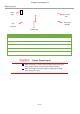
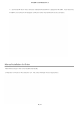
Below picture shows the pin map of connectors. There are two different pins according to servo motor's communication
protocol. (For TTL/PWM, 3pin connector. For RS
[ 3Pins Cable Connector PIN Figure ]
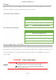
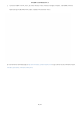
[ 4Pins Cable Connector PIN Figure]
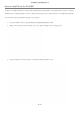
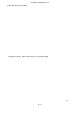
How to Supply Power to IR-
USB01
IR-USB01
's power input voltages are 7.4V or 12.1V, so
input voltage. For 7.4V version mightyZAP
, put 7.4V input power to IR
input power to IR-
USB01. This means that user CANNOT use different voltage versions of mightyZAP at the same time
through IR-USB01.
Caution
Make sure polarity (+/
PCB). Improper polarity connection brings damage of product.
Make sure to apply correct input voltage corresponding the voltage
user's servo.(7.4V or 12V)
IR-USB01 User Manual V1.0
4 / 9
Below picture shows the pin map of connectors. There are two different pins according to servo motor's communication
protocol. (For TTL/PWM, 3pin connector. For RS
-485, 4pin connector is included)
[
USB01
's power input voltages are 7.4V or 12.1V, so
user needs to put proper voltage to the servo
, put 7.4V input power to IR
-
USB01 and for 12.1V version of mightyZAP, put 12.1V
USB01. This means that user CANNOT use different voltage versions of mightyZAP at the same time
3Pins
connector
GND Servo Power -
VCC Servo Power +
SIGNAL Servo
data communication
4Pins
connector
D- RS-485
communication
D+ RS-485
communication
VCC Servo Power (+)
GND Servo Power (-)
Caution
Proper Power Input!
Make sure polarity (+/
-
) when connect the power (see the back side of
PCB). Improper polarity connection brings damage of product.
Make sure to apply correct input voltage corresponding the voltage
user's servo.(7.4V or 12V)
Below picture shows the pin map of connectors. There are two different pins according to servo motor's communication
user needs to put proper voltage to the servo
according to user's servo
USB01 and for 12.1V version of mightyZAP, put 12.1V
USB01. This means that user CANNOT use different voltage versions of mightyZAP at the same time
connector
- for TTL
data communication
(Half duplex)
connector
– RS485
communication
Data (-)
communication
Data (+)
) when connect the power (see the back side of
PCB). Improper polarity connection brings damage of product.
Make sure to apply correct input voltage corresponding the voltage