
_R-STS01mightyZAP Servo Tester Shield Manual_ENG_V1.2 19D5

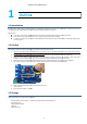

IR-
STS01 Servo Tester Shield Manual V.1.1
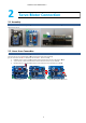
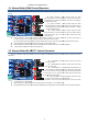
3.1. Manual Mode (PWM
Slide down “Mode 0”
switch. Connect servo motor to Ch.1 using 3pin connector and control position using Position volume (#8
below).
Rotary volume#4 :
Under manual mode,
connected to CH.5.
Also, user may set Min. stroke limit of the servo motor at CH.1.
(
In case that Min Stroke value is bigger than Max Stroke value on CH.1 servo motor, IR
Slide volume#8 :
As stated above, Control position
Mode Switches#9 :
If Mode 1 switch slides UP, Min/Max Stroke setting value of Ch.1 will Not be applied.
3 pin ports#11 : PWM ports for each Chann
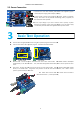
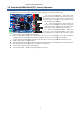
3.2. Manual Mode (RS-
485/TTL
Slide down “Mode 0”
switch. Connect servo motor to TTL(3pins) or RS
(#8 below).
connected to TTL or RS-
485 ports.
Slide volume#8 :
As stated above, Control position
Mode Switches#9 :
If Mode 1 switch slides UP,
STS01 Servo Tester Shield Manual V.1.1
6
Control)Operation
switch. Connect servo motor to Ch.1 using 3pin connector and control position using Position volume (#8
Rotary volume#1 :
Under manual mode, this white
rotary volume
#1 is to control position for the servo motor which is
connected to CH.2.
Under manual mode, this volume is nothing to
do with delay function.
Rotary volume#2 :
Under manual mode, this white
rotary volume#2 is to control position for the servo motor which is
connected to CH.3.
Under manual mode, this volume is nothing
to do with Speed function.
Rotary volume#3 :
Under manual mode, this white
rotary volume#3 is to control position for the servo motor which is
connected to CH.4.
Also, user may set Max. stroke limit of the
servo motor at CH.1.
Under manual mode,
this white rotary volume#4 is to control position for the servo motor which is
Also, user may set Min. stroke limit of the servo motor at CH.1.
In case that Min Stroke value is bigger than Max Stroke value on CH.1 servo motor, IR
-
STS01
As stated above, Control position
which is connected to CH.1.
If Mode 1 switch slides UP, Min/Max Stroke setting value of Ch.1 will Not be applied.
3 pin ports#11 : PWM ports for each Chann
el(Ch1~5)
485/TTL
Control) Operation
switch. Connect servo motor to TTL(3pins) or RS
-
485(4pins) port and control position using Position volume
TTL PORT#12 :
Connect PT version servo motor using 3
pin connector wire.
RS-485 PORT#13 :
Connect F version servo motor using
4pin connector wire.
DATA SELECT#7 :
For TTL/RS
swtich must be at
UART side all the time.
down,
3 pin and 4 pin connector ports will be used for I/O devices
such as sensors, etc. So, make sure this switch slides UP all the time
for TTL/RS-485 communication.
Rotary volume#3 :
User may set Max. stroke limit of the
servo motor connected to TTL or
RS
Rotary volume#4 :
User may set Min. stroke limit of the servo motor
485 ports.
As stated above, Control position
which is connected to TTL or RS-
485 ports.
If Mode 1 switch slides UP,
Min/Max Stroke setting value of connected servo motor will Not be applied.
switch. Connect servo motor to Ch.1 using 3pin connector and control position using Position volume (#8
Under manual mode, this white
#1 is to control position for the servo motor which is
Under manual mode, this volume is nothing to
Under manual mode, this white
rotary volume#2 is to control position for the servo motor which is
Under manual mode, this volume is nothing
Under manual mode, this white
rotary volume#3 is to control position for the servo motor which is
Also, user may set Max. stroke limit of the
this white rotary volume#4 is to control position for the servo motor which is
STS01
will substitute each value.)
If Mode 1 switch slides UP, Min/Max Stroke setting value of Ch.1 will Not be applied.
485(4pins) port and control position using Position volume
Connect PT version servo motor using 3
Connect F version servo motor using
For TTL/RS
-485 communication, this
UART side all the time.
When this swtich slides
3 pin and 4 pin connector ports will be used for I/O devices
such as sensors, etc. So, make sure this switch slides UP all the time
User may set Max. stroke limit of the
RS
-485 ports.
User may set Min. stroke limit of the servo motor
485 ports.
Min/Max Stroke setting value of connected servo motor will Not be applied.