
_R-STS01mightyZAP Servo Tester Shield Manual_ENG_V1.2 19D5


IR-
STS01 Servo Tester Shield Manual V.1.1
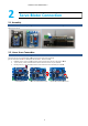
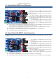
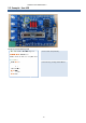
2.3. Power Connection
3
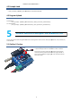
Basic
Test
Test the motion of mightyZAP servo motor using basic operation program stored in IR
There are two modes in basic o
peration
<Manual mode>
Manual mode :
Connect the power and Connect the servo motor with IR
marked above)” to set “
Maunal mode
motor.
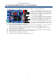
Auto mode :
Connect the power and Connect the servo motor with IR
above)” to set “AUTO mode”
. Using white rotary volumes on left side and red slide switches, user is able to control
position, speed and max/min stroke limit.
STS01 Servo Tester Shield Manual V.1.1
5
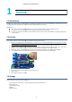
To operate servo motor with IR-
STS01, power needs to be supplied by proper
method like power supply, power adaptor
, or battery.
Connect power to Power input port(#5 on the photo)
circuitry, servo motor can be protected when wrong polarity is applied, but
servo motor will not be operated.
Make sure input voltage of your servo motor as well as polarity of
connection. For example, if your servo input voltage is 7.4V, you need to apply
7.4V electricity and 12V needs to be applied for 12V input servo motor.
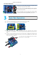
Test
Operation
Test the motion of mightyZAP servo motor using basic operation program stored in IR
-
STS01.
peration
program. - Auto Mode and Manual Mode.
<Auto mode>
Connect the power and Connect the servo motor with IR
-
STS01. Slide
Maunal mode
”
. Then, move black lever(yellow marked above) side to side to operate the servo
Connect the power and Connect the servo motor with IR
-
STS01. Slide UP
. Using white rotary volumes on left side and red slide switches, user is able to control
position, speed and max/min stroke limit.
Please make sure that Data select
UART side all the time. (see the photo left)
STS01, power needs to be supplied by proper
, or battery.
Connect power to Power input port(#5 on the photo)
. Thanks to protection
circuitry, servo motor can be protected when wrong polarity is applied, but
Make sure input voltage of your servo motor as well as polarity of
power
connection. For example, if your servo input voltage is 7.4V, you need to apply
7.4V electricity and 12V needs to be applied for 12V input servo motor.
STS01.
STS01. Slide
DOWN “Mode 0 Switch(Red
. Then, move black lever(yellow marked above) side to side to operate the servo
STS01. Slide UP
“Mode 0 Switch(Red marked
. Using white rotary volumes on left side and red slide switches, user is able to control
Please make sure that Data select
switch must be located at
UART side all the time. (see the photo left)