Robust Mini Linear Servo Motor ------ mightyZAP Servo Tester Shield User Manual
IR-STS01 Servo Tester Shield Manual V.1.1 INDEX 01 Outline 3 06 Servo Control Example by Arduino IDE 20 6.1. Outline/Caution ------------------------------------------20 6.2. Example – Information Read (TTL/RS-485)--------21 6.3. Example – Servo ID---------------------------------------22 6.4. Example – LED---------------------------------------------23 6.5. Example – Limit Temperature-------------------------23 6.6. Example – Goal Position---------------------------------24 6.7.
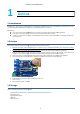
IR-STS01 STS01 Servo Tester Shield Manual V.1.1 1 Outline 1.1 Introduction IR-STS01, Servo Tester Shield is Arduino Shield to operate/test mightyZAP more easily on Arduino Uno & Leonardo. User may connect/operate/test mightyZAP linear servo motor with IR-STS01 IR without PC connection. Main features: Servo Test : User may test mightyZAP linear servo motions using basic motion program stored in the tester. User motion : User may create / control user’s user motion using our Servo Arduino Library.
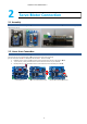
IR-STS01 STS01 Servo Tester Shield Manual V.1.1 2 Servo Motor Connection 2.1. Assembly IR-STS01 is an Arduino shield designed for Arduino Uno and Arduino Leonardo. Assemble Test Shield onto the Arduino Board gently aligning pin structure. 2.2. Linear Servo Connection There are 3 different communication method with IR-STS01. IR Check out your servo’ss communication mode and connect to proper port accordingly. [(Ex) PT version like L12-20PT-3 : PWM/TTL ,F like L12-20F-3 Version : RS-485] 1.
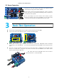
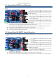
IR-STS01 STS01 Servo Tester Shield Manual V.1.1 2.3. Power Connection To operate servo motor with IR-STS01, STS01, power needs to be supplied by proper method like power supply, power adaptor,, or battery. Connect power to Power input port(#5 on the photo). photo) Thanks to protection circuitry, servo motor can be protected when wrong polarity is applied, but servo motor will not be operated. Make sure input voltage of your servo motor as well as polarity of power connection.
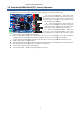
IR-STS01 STS01 Servo Tester Shield Manual V.1.1 3.1. Manual Mode (PWM Control)Operation Slide down “Mode 0” switch. Connect servo motor to Ch.1 using 3pin connector and control position using Position volume (#8 below). Rotary volume#1 : Under manual mode, this white rotary volume#1 #1 is to control position for the servo motor which is connected to CH.2. Under manual mode, this volume is nothing to do with delay function.
IR-STS01 STS01 Servo Tester Shield Manual V.1.1 3.3. Auto Mode(PWM/RS--485/TTL Control) Operation Under Auto mode, user may create their own motion in limited range and operate it automatically. Slide UP Mode 0 switch ch to set Auto mode. Connect servo motors to PWM or TTL or RS-485 485 ports accordingly. Rotary volume#1 (Delay) : Adjust “Delay” value between the motion (between the commands) for CH.1 servo motor(PWM) or servo motor connected to TTL/RS-485 TTL/RS port.
IR-STS01 STS01 Servo Tester Shield Manual V.1.1 4 Use Arduino Library Our dedicated Arduino API can be downloaded from our website at http://www.irrobot.com/ ( Go to “Digital achieves” Linear servo motors). Basic motion is already stored in IR-STS01 IR and user is able to test servo motors with basic motion. Arduino API library needs to be downloaded if users want to create their own motion using IR-STS01 IR on Arduino IDE. To use Arduino API, follow below steps. 1.
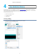
IR-STS01 STS01 Servo Tester Shield Manual V.1.1 4.2 Example Load 1. Start Arduino IDE 2. [File] - [Example] - [IRROBOT_ServoTesterShield] – Select desired example. 4.3 Program Upload Upload proper Examples according Arduino Board brand.
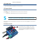
IR-STS01 STS01 Servo Tester Shield Manual V.1.1 5.2. Example - User LED Control LED on IR-STS01. Example for periodical flickering of LED Source to flicker LED periodically. Control LED using “onLED(), offLED” function.
IR-STS01 Servo Tester Shield Manual V.1.1 5.3.Example- VR Read There are 6 x VRs on IR-STS01. User may control stroke, delay, speed and position of mightyZAP using these VRs. Example for VR value output on Serial monitor Source to display VR (VR1~VR6) value on Serial monitor when user changes VR physically. Buad rate setting of serial monitor with “Serial.begin()” function. Read ADC value with “read()” function. Output ADC value with “Serial.print()” function. Range of VR value output is between 0~1023.
IR-STS01 Servo Tester Shield Manual V.1.1 5.4. Example- SWITCH There are 3 x red slide switches on IR-STS01. Users may assign their own function for each mode switch to make various functions. Example to output logical value of mode switches on Serial monitor Example to output logical value of mode switch on serial monitor. -Buad rate setting of serial monitor “Serial.begin()” function. -Read logical value with “read()” function. -Output logical value with “print()” function.
IR-STS01 Servo Tester Shield Manual V.1.1 5.5.Example-Servo Motor PWM Control 1 There are 5 x PWM channels on IR-STS01 to control “PT” version mightyZAP. To operate mightyZAP Servo motor, user needs to connect proper power (12V or 7.4V according to the input voltage of user’s servo). Power source can be Power supply, power adaptor, or battery and connect the power line to Green power connector below. Example to control mightyZAP using PWM Prepare test by opening new file on Arduino IDE.
IR-STS01 STS01 Servo Tester Shield Manual V.1.1 5.6.Example-Servo Motor PWM Control 2 Select [IRROBOT_ServoTesterShield] – [UNO] [UNO or[LEO] –[ServoTester_ Knob] Read VR value using “analogRead()” command to control servo motor position. Example to control servo motor using VR Source to control servo motor using VR value. Read VR value by “read()”” function to control servo motor position. Read value range is between 0~1023.
IR-STS01 STS01 Servo Tester Shield Manual V.1.1 5.7.Example - Stroke Limit (PWM Control) Select [IRROBOT_ServoTesterShield] – [UNO] [UNO or [LEO] –[ServoTester_StrokeLimit] Control Max / Min stroke limit by Rotary volumes#3 and 4. Source to set Max/Min stroke limit by reading two VR values. Read each VR value by “Read()” function to set Max/Min stroke limit. Read value range is between 0~1023. Compare stroke limit value with goal position value.
IR-STS01 STS01 Servo Tester Shield Manual V.1.1 5.8. VR Reverse (PWM Control) Control Select [IRROBOT_ServoTesterShield] – [UNO/LEO] –[ServoTester_VR_Reverse] Control Max / Min stroke limit by Rotary volumes#3 and 4. Source to set Max/Min stroke limit by reading two VR values. Compare max and min stroke limit and replace its value if min value is bigger than max value.
IR-STS01 STS01 Servo Tester Shield Manual V.1.1 5.9. Example - VR Speed (PWMControl) (PWM Select [IRROBOT_ServoTesterShield] – [UNO]or[LEO] [UNO –[ServoTester_VR_Speed] Control Speed of servo motor by rotary knob#2. Read VR value for present resent position and adjust it to goal position. According to VR value, time to approach goal position will be differentiated. To prevent stopping condition of servo motor, adjust scale value between 3~ 1023.
IR-STS01 STS01 Servo Tester Shield Manual V.1.1 5.10. Example - VR Delay (PWMControl) (PWM Select [IRROBOT_ServoTesterShield] – [UNO] [UNO or[LEO] –[ServoTester_VR_Delay] Control delay by Rotary volume#1. Adjust delay value by adjusting VR#1 value after reading it. According to the value of VR, time to approach goal position will be differentiated. Adjust delay value between 0~50. Count/update delay time in Program loop, and reset delay count.
IR-STS01 Servo Tester Shield Manual V.1.1 5.11 Data Communication Control(TTL/RS-485) IR-STS01 has each TTL(3pins) and RS-485(4pins) ports. Multiple qty of servo motors can be connected each other in serial (daisy-chain). To operate servo motor, power needs to be supplied(12V or 7.4V) by power supply, adaptor or battery. To get feedback Echo packet for servo motor status, user needs to use Leonardo board which has two serial ports. Below example is simple packet command.
IR-STS01 STS01 Servo Tester Shield Manual V.1.1 6 Servo Control Example through Arduino IDE Control servo motor via data communication (RS-485 (RS or TTL) on Arduino IDE. Control ntrol is available using our IR-STS01 IR Arduino servo tester shield or Arduino board only. 6.1 Outline To upload example, Data select switch must be at UP position. Basic program from the factory will be removed and rewrote by user program once user uploadss example.
IR-STS01 Servo Tester Shield Manual V.1.1 6.2. Example - Information Read (RS-485/TTL) Example to read basic information such as ID, Version using API of MightyZap. Select [Example] - [MightyZap] - [UNO]or[LEO]–[ServoTester_Information] . #deifne ID_NUM / servo ID Assignment • Function : Assign servo ID number for control. • Servo Motor ID - 0 : Default setting value. Stand-alone ID(hereinafter, 0 will be used as an ID for all examples.) - 1 ~ 253 : Individual ID from 1 to 253. - 254 : Broadcasting ID.
IR-STS01 Servo Tester Shield Manual V.1.1 • Parameter - ID_NUM : Servo motor ID Tester.Mightyzap.Virsion(nt ID_NUM)/Parameter Read • Function : Servo motor version check • Parameter - ID_NUM : Servo motor ID Tester.Mightyzap.
IR-STS01 Servo Tester Shield Manual V.1.1 6.4. Example - LED Setting LED color using LedON() command. Select [Example] - [MightyZap] - [UNO]or [LEO]– [ServoTester_ LED] Change LED color using LedON() command. Use RED, GREEN, BLUE to express various color. LED alarm is the highest priority. Tester.Mightyzap.
IR-STS01 Servo Tester Shield Manual V.1.1 6.6. Example - Goal Position Example to control servo motor position using goalPosition() command. Select [Example] - [MightyZap] - [UNO]or[LEO]–[ServoTester_ goalPosition] By 1sec interval, control position between 0 ~ 4095. Change position value in goalPosition(ID_NUM,0) function and check position difference. Tester.Mightyzap.
IR-STS01 Servo Tester Shield Manual V.1.1 6.7. Example - Present Position Example to check current position of servo motor using presentPosition() command. Select [Example] - [MightyZap] - [UNO]or[LEO]–[ServoTester_ presentPosition] After changing position using goalPosition() command, check real-time present position by presentPosition() command. *Moving() : to check operation status (no moving or moving) (1 : Moving, 0: Moving Stop) Tester.Mightyzap.
IR-STS01 Servo Tester Shield Manual V.1.1 6.8. Example - Limit Volt Check/setting input voltage limit by LimitVolt() command. Select [Example] - [MightyZap] - [UNO]or[LEO]–[ServoTester_ LimitVolt] Check/setting input voltage max/min limit by LimitVolt() command. Change “Lowest” to “Highest” in LimitVolt(IN_NUM, Lowest, LimitVolt) to change voltage limit setting In case of out of limit input voltage, servo to be operated according to alarm setting. Tester.Mightyzap.
IR-STS01 Servo Tester Shield Manual V.1.1 6.9. Example - Alarm LED Setting LED Alarm indicator by AlarmLed() Select [Example] - [MightyZap] - [UNO]or[LEO]–[ServoTester_ AlarmLed] alarmLed() - When Error occurs, LED will be ON if bit is set at 1. (1=enable / 0=disable) Example shows flickering LED operation and low bit has a priority when different errors occur at the same time. After error condition is resolved, alarm will be inactivated after 2 sec and return to normal status. . Tester.Mightyzap.
IR-STS01 Servo Tester Shield Manual V.1.1 6.10. Example - AlarmShutdown Example for alarm shutdown(power cut off when error occurs) using AlarmShutdown() command. Select [Example] - [MightyZap] - [UNO] or [LEO]–[ServoTester_ AlarmShutdown] alarmShutdown() When error occurs, power will be off(servo shutdown) to protect servo motor. Setting bit as 1, this function will be enabled.
IR-STS01 Servo Tester Shield Manual V.1.1 6.11.Example - Stroke Limit Example to set stroke limit(limit for position) using StrokeLimit() command. Select [Example] - [MightyZap] - [UNO] or[LEO]–[ServoTester_ StrokeLimit] 1.StrokeLimit() - Setting max(long)/min(short) position limit to control servo motor position’s limit. - User may decrease max(long) stroke limit or increase min(short) stroke limit. 2. Shot Stroke(A) Long Stroke(C) Tester.Mightyzap .
IR-STS01 Servo Tester Shield Manual V.1.1 6.12.Example - Resolution Factor Example to set Resolution of servo motor position using ResolutionFactor() command. Select [Example] - [MightyZap] - [UNO/LEO]–[ServoTester_ ResolutionFactor] - - ResolutionFactor() Change positional resolution of Servo motor to 512/1024/2048/4096 (default : 4096) The Higher resolution, the higher positional accuracy Resolution factor can be changed by serial communication. Tester.Mightyzap.
IR-STS01 Servo Tester Shield Manual V.1.1 6.13. Moving Speed Example to set servo motor speed using MovingSpeed() command. Select [Example] - [MightyZap] - [UNO/LEO]–[ServoTester_ MovingSpeed] 1.movingSpeed() - Set moving speed. - 0 : Max speed - 1~1023 : the higer value, the faster speed. - To be initialized to 0 when Power is applied again. 2.Check operation status by moving() function. (1 : moving, 0: not moving) 3. Change servo motor speed by serial communication and check its motion. Tester.
IR-STS01 Servo Tester Shield Manual V.1.1 6.14 Force Limit Example to set Force limit by ForceLimit() command. Select [Example] - [MightyZap] - [UNO/LEO]–[ServoTester_ ForceLimit] ForceLimit() - Servo motor force limit setting - Set between 0~1023. The higher value, the stronger force. - when Power is applied again, Max force value will be copied to Force limit value. Change force by ForceLimit() function and check operation status. The lower force may make slower operation. Tester.Mightyzap.
IR-STS01 Servo Tester Shield Manual V.1.1 6.15. Max Force Example to set Max force by using MaxForce() command. Select [Example] - [MightyZap] - [UNO/LEO]–[ServoTester_MaxForce] The function of Max force is same as Force limit described previously. But Max force is non- volatile value, so it will not be removed even after power off while Force limit is a volatile parameter and will be removed when power is off. Thus, Max force setting will be copied to Force limit value when the servo reboots.
IR-STS01 Servo Tester Shield Manual V.1.1 6.16. Compliance Margin Set maximum positional error allowance using ComplianceMargin() command. Select [Example] - [MightyZap] - [UNO/LEO]–[ServoTester_ComplianceMargin] complianceMargin() - Set maximum positional error allowance - The higher compliance margin, the higher deadband. The lower compliance margin, the higher accuracy, but the higher chance of jitter. Compliance margin can be set for each retract(short) and extend(long) direction.
IR-STS01 Servo Tester Shield Manual V.1.1 6.17. Punch Set current amount of servo motor using Punch() command. Select [Example] - [MightyZap] - [UNO/LEO]–[ServoTester_Punch] m_zap.Punch() Punch is a minimum current for servo motor operation. The higher punch value, the higher stall torque, but the higher chance of jitter if it is too high. Check minimum operating current of servo motor using Punch() function. Control minimum operating current of servo motor using Punch() function.
IR-STS01 Servo Tester Shield Manual V.1.1 6.18. Punch Initial Set initial current of servo motor using PunchInitial() command. Select [Example] - [MightyZap] - [UNO/LEO]–[ServoTester_PunchInitial] PunchInitial() - Set punch initial value. Punch initial value will be saved at Punch parameter when power is applied to servo motor. After changing Punch initial value, Check saved Punch initial value by applying power again (reboot). Tester.Mightyzap.
IR-STS01 Servo Tester Shield Manual V.1.1 6.19. PID Set optimal operation of servo motor using PID command. Select [Example] - [MightyZap] - [UNO/LEO]–[ServoTester_PID] pidGain() - Set each PID value of Servo motor After setting each PID value, check the difference of operation. Put each PID value with a space in Serial window as below. 20 18 32 Tester.Mightyzap.
IR-STS01 Servo Tester Shield Manual V.1.1 [Appendix - Arduino PC Development Environment Setting] IR-STS01, Arduino Servo Tester Shield can be used with Arduino Uno or Arduino Leonardo. User needs to set Arduino development environment as below for program operation. 1 Install Arduino IDE 1. Select Window installer from https://www.arduino.cc/en/main/software 2.Download by “JUST DOWNLOAD”. 3. Run arduino-1.8.2.exe after download.
IR-STS01 Servo Tester Shield Manual V.1.1 4. Install software as following.
IR-STS01 Servo Tester Shield Manual V.1.1 5. Install driver when Windows asks it. 6. Click “Close” after installation. 7. Run “Arduino” on your Windows wallpaper.
IR-STS01 Servo Tester Shield Manual V.1.1 2. Arduino IDE Basic Composition Basic composition of Arduino IDE is as below. Compile button Upload button Serial monitor button Message area 1. Compile button : Program will be compiled. (Compile result to be shown at area#4) 2. Upload button : Upload to Arduino at the same time of compile (In case of compile error or Arduino & usb connection error occur, it will be shown at area#4.) 3.