
EZ Controller User Manual_ENG_21E21_V2

EZ Controller User Manual_EN_V.2.0
4
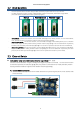
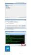
Set the positions of the A and B points by adjusting the blue V/R ③ (A
position) and ④ (B position) respectively.
-Clockwise:- (actuator retraction direction)
-Counterclockwise: + (actuator extension direction)
For convenience, it is recommended to set A to minimum position and B
to maximum position as shown below.
-A point (part ③): Turn clockwise to set the minimum position
-B point (part ④): Turn counterclockwise to set the maximum position
Please note that the minimum and maximum positions of A and B may
be reversed and changed depending on user settings.
2
Function & Operation
2.1 Function
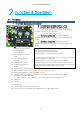
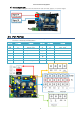
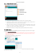
EZ Controller Components and Description
①
A Position External switch input (○: +, ●:-)
②
B Position External switch input (○: +, ●:-)
: Position command by external switch or external signal.
It is same function as ⑨,⑩ push button.
: For position setting, use ③ and ④
③
“A” Position setting V/R
: “A” position setting by
adjusting variable resistor. (A position command made by ①
or ⑨)
④
“B” Position setting V/R :
“B” position setting by
adjusting variable resistor. (B position command made by ②
or ⑩)
⑤
PC
connection micro USB
terminal : Arduino Sketch
download/Serial
communication
⑥ Reset Switch: Controller
reset
⑦ 12V main power input
terminal
⑧ Mode selection Switch
⑨ A Position push button
Switch
⑩ B Position push button Switch
⑪ MCU F/W download connector(ICSP) : User manipulation prohibited
⑫ Arduino I/O 핀(Digital:3 , Analog:3 / GND, 12V, SIG)
⑬ Internal power terminal(GND / 3.3V / 5V / 12V) : power output terminal internally used.
[Current Limit of each terminal]
- 3.3V : ~150mA / 5V : ~ 900 mA / 12V : Depending on Input Voltage Source
⑭ PWM port
⑮ TTL port
⑯ RS-485 port
⑰ Linear Potentiometer for manual position
⑱ User external communication terminal (Bluetooth : TX / RX / GND / 3.3V)
⑯
①
②
③
⑤
⑧
⑨
⑩
⑪
⑫
⑬
⑭
⑮
⑥
④
⑦
⑰
⑱
○
●
○
●