
EZ Controller User Manual_ENG_21E21_V2

EZ Controller User Manual_EN_V.2.0
21
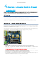
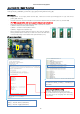
4.10. Example –Stroke Limit
Example which can set the max/min limit of stroke with 2 x position setting variable resistors(fig#3&4).
Select [Example] - [IRROBOT_EZController] - [EZ]–[EasyControl _StrokeLimit]
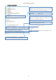
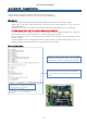
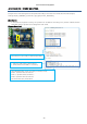
[Description]
- Mode switch (#8) can be positioned anywhere. (Mode switch only works in the built-in basic program)
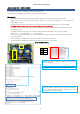
- Supply power to the input power terminal (#7). Make sure correct input voltage(7.4V or 12V) and correct
polarity.(GND and VCC)
- Carefully insert the connector suitable for the selected communication. (#14 PWM / #15 TTL / #16 RS-485)
-
(For PWM connector (#14), refer to the page 6 to make sure correct polarity.)
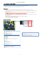
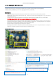
- Set the position limit by turning the variable resistors (Fig# 3 and 4) that adjust the position of the max and min
points of the stroke in the clockwise (-) and counterclockwise (+) directions. Clockwise direction is for retraction
(short stroke), Counterclockwise direction is for extension(long stroke).
- Operate actuator by adjusting linear potentiometer (Fig#17).
Operating position will be affected by position setting V/R(#3&4), and even if the potentiometer is moved, the
position is controlled only within the section set by the variable resistor.
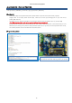
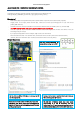
[Program Description]
Regardless of V/R(#3&4) location, large value sets
max limit and small value sets min limit.
Determine the potentiometer value so that linear
potentiometer does not exceed the set range.