
EZ Controller User Manual_ENG_21E21_V2

EZ Controller User Manual_EN_V.2.0
18
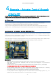
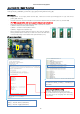
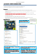
4.7. Example -Extra IO(2)
Controlling the actuator by receiving the input of an external sensor to the analog IO pin.
Select [Example] - [IRROBOT_EZController] - [EZ]–[EasyControl_Sensing]
[Description]
- Mode switch (#8) can be positioned anywhere. (Mode switch only works in the built-in basic program)
- Supply power to the input power terminal (#7). Make sure correct input voltage(7.4V or 12V) and correct
polarity.(GND and VCC)
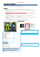
- Carefully insert the connector suitable for the selected communication. (#14 PWM / #15 TTL / #16 RS-485)
(For PWM connector (#14), refer to the page 6 to make sure correct polarity.)
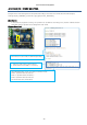
- Among the header pins (# 12), the right three are analog terminals, and these three pins are used for Extra IO.
(See picture below)
- Connect the sensor to read the analog value to the pin according to the purpose.
- Actuator moves according to the sensor value.
ex) CDS => brighter forward, darker backward
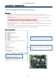
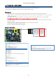
[Program Description]
●
GND
●
5V
●
SIG
In the library, analog pins A0, A2, A3 are defined as VR_4,
VR_5, VR_6.
Declare the pin you want to use with a defined name, or
directly declare matched analog pin.