
EZ Controller User Manual_ENG_21E21_V2

EZ Controller User Manual_EN_V.2.0
17
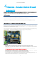
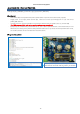
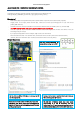
4.6. Example –Extra IO(1)
Controlling the actuator by receiving the input of the digital IO pin.
Select [Example] - [IRROBOT_EZController] - [EZ]–[EasyControl_ExtIO]
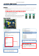
[Description]
- Mode switch (#8) can be positioned anywhere. (Mode switch only works in the built-in basic program)
- Supply power to the input power terminal (#7). Make sure correct input voltage(7.4V or 12V) and correct
polarity.(GND and VCC)
- Carefully insert the connector suitable for the selected communication. (#14 PWM / #15 TTL / #16 RS-485)
(For PWM connector (#14), refer to the page 6 to make sure correct polarity.)
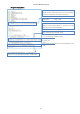
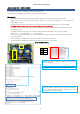
- The left three of the upper header pins (# 12) are assigned for digital terminals, and the first & second pins from
the left can be used.
- The signal terminal is the lowest pin of the 3 pins and the pin has a signal level of 5V. (See picture below)
(Active Low / 5V : High Signal / 0V : Low Signal)
- Set the two points for position setting in the same way as the previous method through the two variable resistors
on the left (#3 and 4).
- When a low signal is applied to the first pin, the actuator moves to the set point A,
When a low signal is applied to the second pin, the actuator moves to the set B point.
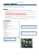
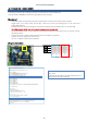
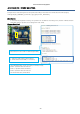
[Program Description]
●
GND
●
5V
●
SIG
The left three pins are Arduino's Digital IO, the right three
pins are Analog IO.
Among Digital IO (7,11,13), 7 and 11 IO are declared as input.
When 5V signal is applied to pin 7, the actuator moves to
the set point A. When 5V signal is applied to pin 11 the
a
ctuator moves to the set point
B.