EZ Controller (IR-CT01) User Manual
EZ Controller User Manual_EN_V.2.0 INDEX 01 Overview 3 1.1. Precautions------------------------------3 1.2. Proper Storage---------------------------3 02 Function & Operation 4 2.1. Function----------------------------------4 2.2. Mode Selection---------------------------5 2.3. External Switch and Signal Input---------5 2.4. Parts Pin Map-----------------------------6 03 PC Installation for Arduino IDE 7 3.1.Install Arduino IDE-----------------------7 3.2.
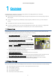
EZ Controller User Manual_EN_V.2.0 1 Overview Arduino-based EZ Controller is a controller to easily operate / test mightyZAP linear servo actuators. The features of EZ Controller are as follows. Operate the linear actuator simply and easily through various input devices on the board by using the built-in basic program. Various motion programming is available by example program provided from us or by your own coding via Arduino. Connectable with various external accessories. (External switch, etc.
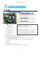
EZ Controller User Manual_EN_V.2.0 2 Function & Operation 2.1 Function ○ ① ● ○ ② ● ⑭ ④ : For position setting, use ③ and ④ ⑧ ⑨ ⑩ ⑦ ⑱ ⑥ ⑦ ⑧ ⑨ ⑩ ⑪ ⑫ ⑬ ⑭ ⑮ ⑮ ⑯ ⑰ ⑤ : Position command by external switch or external signal. It is same function as ⑨,⑩ push button.
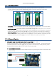
EZ Controller User Manual_EN_V.2.0 2.2 Mode Selection Test the operation of the actuator using the basic operation program built into the EZ Controller. The basic operation program consists of Manual Mode, Position Select Mode, and Position Toggle Mode. (The mode switch only affects the basic operation program.) Manual Position Select Position Toggle Manual Mode : Connect the actuator, move the Mode switch(⑧) to the lowest position, set it to Manual Mode.
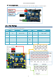
EZ Controller User Manual_EN_V.2.0 2) External Signal Input : To recognize the signal in the second hole of each terminal, apply 3.3~12V level signal. 2.4 Part Pinmap - Parts No : Part number described on the manual Page 4.
EZ Controller User Manual_EN_V.2.0 3 PC Installation for Arduino IDE IR-CT01, EZ controller has been built based on Arduino Leonardo. User needs to set Arduino development environment as below for program operation. 3.1. Install Arduino IDE 1. Select Window installer from https://www.arduino.cc/en/main/software 2.Download by “JUST DOWNLOAD”. 3. Run arduino-xxx-windows.exe after download.
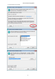
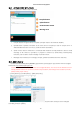
EZ Controller User Manual_EN_V.2.0 4. Install software as following.
EZ Controller User Manual_EN_V.2.0 5. Install driver when Windows asks it. 6. Click “Close” after installation. 7. Run “Arduino” on your Windows wallpaper.
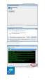
EZ Controller User Manual_EN_V.2.0 3.2. Arduino IDE Structure Basic composition of Arduino IDE is as below. Compile button Upload button Serial monitor button Message area 1. Compile button :Program will be compiled. (Compile result to be shown at area#4) 2. Upload button :Upload to Arduino at the same time of compile (In case of compile error or Arduino&usbconnection error occur, it will be shown at area#4.) 3.
EZ Controller User Manual_EN_V.2.0 3.4. Example Loading 1. Run Arduino IDE 2. Click [File] - [Examples] - [IRROBOT_EZController_XX]-[EZ] – Then, select desired example. 3.5. Program Upload 1. Click [Tools]-[Board]-Select [Arduino Leonardo] 2. [Tools]-[Port]-Select connected Port [COMXX (Arduino Leonardo)] 3. Upload program to the board by Upload button.
EZ Controller User Manual_EN_V.2.0 4 Example - Actuator Control through Arduino IDE Actuator control via the Arduino IDE's data communication protocol (RS-485 or TTL). This is for the advanced users of Arduino who want to control actuators more freely through data communication of Arduino. 4.1 Overview Here are Arduino examples to control mightyZAP through EZ Controller. The examples are for serial data communication (TTL or RS-485 communication) and do not support PWM communication.
EZ Controller User Manual_EN_V.2.0 - [Program Description] Example of setting two points with the value of a variable resistor and moving them to the corresponding point when the buttons of A and B are pressed. Mapping for PWM value Short : 900 Long : 2100 Read the variable resistor values of Position A and Position B and assign values to “A_stroke_val” and “B_stroke_val” variables respectively. The map () function maps the variable resistor's resistor value to the actuator's position range.
EZ Controller User Manual_EN_V.2.0 4.3. Example - TogglePosition This is an example of inverting 2 Positions designated by 1 toggling button. Select [Example] - [IRROBOT_EZController] - [EZ]– [EasyControl_TogglePosition] [Description] - Mode switch (#8) can be positioned anywhere. (Mode switch only works in the built-in basic program) - Supply power to the input power terminal (#7). polarity.(GND and VCC) - Carefully insert the connector suitable for the selected communication.
EZ Controller User Manual_EN_V.2.0 4.4. Example –Manual Position Moving the position of the actuator by moving distance of the linear potentiometer. Select [Example] - [IRROBOT_EZController] - [EZ]– [EasyControl_MPosition] [Description] - Mode switch (#8) can be positioned anywhere. (Mode switch only works in the built-in basic program) - Supply power to the input power terminal (#7). polarity.(GND and VCC) - Carefully insert the connector suitable for the selected communication.
EZ Controller User Manual_EN_V.2.0 4.5. Example –Basic Function Switching control mode and controlling actuator through Mode selection slide switch. Select [Example] - [IRROBOT_EZController] - [EZ]-[EasyControl_BasicFunction] 선택 [Description] - Supply power to the input power terminal (#7). polarity.(GND and VCC) Make sure correct input voltage(7.4V or 12V) and correct - Carefully insert the connector suitable for the selected communication.
EZ Controller User Manual_EN_V.2.0 4.6. Example –Extra IO(1) Controlling the actuator by receiving the input of the digital IO pin. Select [Example] - [IRROBOT_EZController] - [EZ]–[EasyControl_ExtIO] [Description] - Mode switch (#8) can be positioned anywhere. (Mode switch only works in the built-in basic program) - Supply power to the input power terminal (#7). polarity.(GND and VCC) - Carefully insert the connector suitable for the selected communication.
EZ Controller User Manual_EN_V.2.0 4.7. Example -Extra IO(2) Controlling the actuator by receiving the input of an external sensor to the analog IO pin. Select [Example] - [IRROBOT_EZController] - [EZ]–[EasyControl_Sensing] [Description] - Mode switch (#8) can be positioned anywhere. (Mode switch only works in the built-in basic program) - Supply power to the input power terminal (#7). polarity.(GND and VCC) - Carefully insert the connector suitable for the selected communication.
EZ Controller User Manual_EN_V.2.0 4.8. Example –External Communication Controlling the actuator through external communication by the Bluetooth port. Select [Example] - [IRROBOT_EZController] - [EZ]–[EasyControl_ExtCom] [Description] - Mode switch (#8) can be positioned anywhere. (Mode switch only works in the built-in basic program) - Supply power to the input power terminal (#7). polarity.(GND and VCC) - Carefully insert the connector suitable for the selected communication.
EZ Controller User Manual_EN_V.2.0 4.9. Example – Mode Selection Example for the mode setting that can be operated according to the value of the mode selection switch (Fig# 8). Select [Example] - [IRROBOT_EZController] - [EZ]–[EasyControl _ModeSelect] [Description] In the same way as [Basic Function], the operation can be different according to the position of Mode selection switch(#8), and the operation can be assigned for each mode.
EZ Controller User Manual_EN_V.2.0 4.10. Example –Stroke Limit Example which can set the max/min limit of stroke with 2 x position setting variable resistors(fig#3&4). Select [Example] - [IRROBOT_EZController] - [EZ]–[EasyControl _StrokeLimit] [Description] - Mode switch (#8) can be positioned anywhere. (Mode switch only works in the built-in basic program) - Supply power to the input power terminal (#7). polarity.(GND and VCC) - Carefully insert the connector suitable for the selected communication.